Port Diagram

Sales: 408-778-9952 | General: 408-778-4200 | Fax: 408-778-4300
Sales & Customer Support: [email protected]
Tech Support: [email protected]
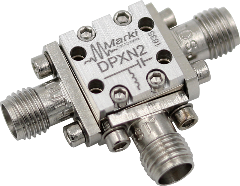
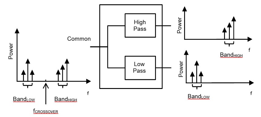
Available in either a connectorized or miniature surface mount package (0.240 inch x 0.150 inch), the DPX-2 is a low cost, high performance diplexer. The unique design offers high pass/low pass signal routing/multiplexing with excellent isolation. Passband insertion loss is less than 1 dB with rejection typically exceeding 25 dB. Besides being ideal for transmitter/receiver applications, the DPX-2 can also be used as an excellent non-reflective low pass (or high pass) filter for systems requiring broadband 50Ω impedance match (such as mixers).

DPXN-2
Diplexer
| Revision Code | Revision Date | Comment |
|---|---|---|
| - | 2022-02-11 | Datasheet Initial Release |
DPXN-2
Diplexer
| Port | Function | Connector Type | Description | DC Equivalent Circuit |
|---|---|---|---|---|
| GND | Ground | - | DPXN package ground path is provided through the metal housing and outer coax conductor. |  |
| Port 1 | RF High Band | - | Port 1 is DC open to Port 2 and Port 3. |  |
| Port 2 | Common/Input | - | Port 2 is DC open to Port 1 and short to Port 3. |  |
| Port 3 | RF Low Band | - | Port 3 is DC open to Port 1 and short to Port 2. | |
DPXN-2
Diplexer
| Parameter | Details | Rating |
|---|---|---|
| Dimensions | - | 11.94 x 11.94 mm |
DPXN-2
Diplexer
Specifications guaranteed from -55 to +100°C, measured in a 50Ω system.
| Parameter | Test Conditions | Minimum Frequency (GHz) | Maximum Frequency (GHz) | Min | Typ | Max | Unit |
|---|---|---|---|---|---|---|---|
| 1 dBc High Passband | Temp = 25°C | - | - | 1.86 | - | - | GHz |
| 3 dBc High Passband | Temp = 25°C | - | - | 2.08 | - | - | GHz |
| 30 dBc High Pass Rejection Point | Temp = 25°C | - | - | 2.08 | - | - | GHz |
| High Passband Return Loss | Temp = 25°C | - | - | - | 5 | - | dB |
| High Pass Isolation | Temp = 25°C | - | - | - | 8 | - | dB |
| High Pass Group Delay | Temp = 25°C | - | - | - | 574 | - | ps |
| 1 dBc Low Passband | Temp = 25°C | - | - | - | - | 7.00 | GHz |
| 3 dBc Low Passband | Temp = 25°C | - | - | - | - | 4.67 | GHz |
| 30 dBc Low Pass Rejection Point | Temp = 25°C | - | - | - | - | 4.67 | GHz |
| Low Passband Return Loss | Temp = 25°C | - | - | - | 16 | - | dB |
| Low Pass Isolation | Temp = 25°C | - | - | - | 26 | - | dB |
| Low Pass Group Delay | Temp = 25°C | - | - | - | 115 | - | ps |
| Crossover Frequency | Temp = 25°C | - | - | - | 1.73 | - | GHz |
| Common Port Return Loss | Temp = 25°C | - | - | - | 15 | - | dB |
| Impedance | Temp = 25°C | - | - | - | 50 | - | Ω |
| 30 dBc Low Pass Rejection Point | <1.5GHz | - | 1.5 | - | 15 | - | dB |
| 30 dBc Low Pass Rejection Point | <1GHz | - | 1 | 25 | 30 | - | dB |
| Common Port Return Loss | <1.5GHz | - | 1.5 | - | 15 | - | dB |
| Common Port Return Loss | - | 2.7 | 7 | - | 15 | - | dB |
| Cross Over Frequency | - | 2.05 | 2.05 | - | 5 | - | % |
| High Pass Filter, Pass Band Insertion Loss | - | 2.7 | 7 | - | 0.6 | 1.2 | dB |
| High Pass Filter, Pass Band Return Loss | - | 2.7 | 7 | - | 15 | - | dB |
| Isolation | <1.4GHz | - | 1.4 | 14 | 25 | - | dB |
| Isolation | - | 2.9 | 7 | 14 | 25 | - | dB |
| Low Pass Filter, Pass Band Insertion Loss | - | 0 | 1.5 | - | 0.6 | 1.2 | dB |
| Low Pass Filter, Pass Band Return Loss | <1.5GHz | - | 1.5 | - | 15 | - | dB |
| Low Pass Filter, Stop Band Rejection | - | 3.5 | 7 | 20 | 25 | - | dB |
| Low Pass Filter, Stop Band Rejection | - | 2.7 | 3.5 | - | 15 | - | dB |
| RF Power | - | - | - | - | - | 1 | W |
| 1 dBc High Passband | - | - | - | 2.7 | - | 7 | GHz |
| 1 dBc Low Passband | - | - | - | 0 | - | 1.5 | GHz |
| Parameter | Test Conditions | Minimum Frequency (GHz) | Maximum Frequency (GHz) | Min | Typ | Max | Unit |
|---|---|---|---|---|---|---|---|
| 1 dBc High Passband | Temp = 25°C | - | - | 1.86 | - | - | GHz |
| 3 dBc High Passband | Temp = 25°C | - | - | 2.08 | - | - | GHz |
| 30 dBc High Pass Rejection Point | Temp = 25°C | - | - | 2.08 | - | - | GHz |
| High Passband Return Loss | Temp = 25°C | - | - | - | 5 | - | dB |
| High Pass Isolation | Temp = 25°C | - | - | - | 8 | - | dB |
| High Pass Group Delay | Temp = 25°C | - | - | - | 574 | - | ps |
| 1 dBc Low Passband | Temp = 25°C | - | - | - | - | 7.00 | GHz |
| 3 dBc Low Passband | Temp = 25°C | - | - | - | - | 4.67 | GHz |
| 30 dBc Low Pass Rejection Point | Temp = 25°C | - | - | - | - | 4.67 | GHz |
| Low Passband Return Loss | Temp = 25°C | - | - | - | 16 | - | dB |
| Low Pass Isolation | Temp = 25°C | - | - | - | 26 | - | dB |
| Low Pass Group Delay | Temp = 25°C | - | - | - | 115 | - | ps |
| Crossover Frequency | Temp = 25°C | - | - | - | 1.73 | - | GHz |
| Common Port Return Loss | Temp = 25°C | - | - | - | 15 | - | dB |
| Impedance | Temp = 25°C | - | - | - | 50 | - | Ω |
| 30 dBc Low Pass Rejection Point | <1.5GHz | - | 1.5 | - | 15 | - | dB |
| 30 dBc Low Pass Rejection Point | <1GHz | - | 1 | 25 | 30 | - | dB |
| Common Port Return Loss | <1.5GHz | - | 1.5 | - | 15 | - | dB |
| Common Port Return Loss | - | 2.7 | 7 | - | 15 | - | dB |
| Cross Over Frequency | - | 2.05 | 2.05 | - | 5 | - | % |
DPXN-2
Diplexer
| Parameter | Test Conditions | Minimum Frequency (GHz) | Maximum Frequency (GHz) | Min | Typ | Max | Unit |
|---|---|---|---|---|---|---|---|
| High Pass Filter, Pass Band Insertion Loss | - | 2.7 | 7 | - | 0.6 | 1.2 | dB |
| High Pass Filter, Pass Band Return Loss | - | 2.7 | 7 | - | 15 | - | dB |
| Isolation | <1.4GHz | - | 1.4 | 14 | 25 | - | dB |
| Isolation | - | 2.9 | 7 | 14 | 25 | - | dB |
| Low Pass Filter, Pass Band Insertion Loss | - | 0 | 1.5 | - | 0.6 | 1.2 | dB |
| Low Pass Filter, Pass Band Return Loss | <1.5GHz | - | 1.5 | - | 15 | - | dB |
| Low Pass Filter, Stop Band Rejection | - | 3.5 | 7 | 20 | 25 | - | dB |
| Low Pass Filter, Stop Band Rejection | - | 2.7 | 3.5 | - | 15 | - | dB |
| RF Power | - | - | - | - | - | 1 | W |
| 1 dBc High Passband | - | - | - | 2.7 | - | 7 | GHz |
| 1 dBc Low Passband | - | - | - | 0 | - | 1.5 | GHz |
DPXN-2
Diplexer


DPXN-2
Diplexer
DPXN-2
Diplexer
