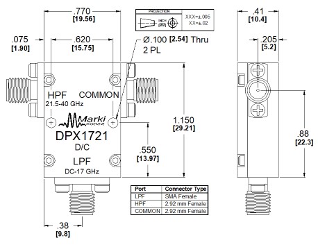
Port Diagram

Sales: 408-778-9952 | General: 408-778-4200 | Fax: 408-778-4300
Sales & Customer Support: [email protected]
Tech Support: [email protected]
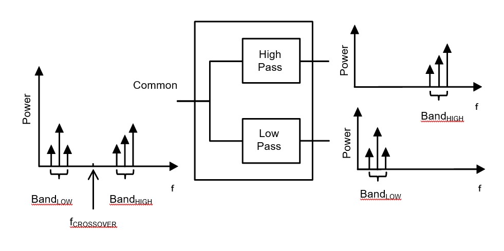
The DPX-1721 is a broadband low pass/high pass diplexer capable of multiplexing low frequency (DC-17 GHz) and high frequency (21.5-40 GHz) signals. The novel design offers extremely low insertion loss and high isolation between the low pass and high pass channels. The DPX-1721 is an excellent solution for applications such as high frequency/baseband signal routing (especially following a broadband high frequency mixing stage), low loss power splitting/combination, separation of harmonic tones, and general-purpose lab use.


| Part Number | Description | Connectors | Green Status | Product Lifecycle | Export Classification |
|---|---|---|---|---|---|
| DPX-1721 | Broadband Diplexer 21.5 - 40 GHz | Standard | Non-RoHS | Released | EAR99 |
| Part Number | Description | Connectors | Green Status | Product Lifecycle | Export Classification |
|---|---|---|---|---|---|
| DPX-1721 | Broadband Diplexer 21.5 - 40 GHz | Standard | Non-RoHS | Released | EAR99 |
DPX-1721
Broadband Diplexer 21.5 - 40 GHz
| Revision Code | Revision Date | Comment |
|---|---|---|
| - | 2014-04-15 | Datasheet Initial Release |
DPX-1721
Broadband Diplexer 21.5 - 40 GHz
| Port | Function | Connector Type | Description | DC Equivalent Circuit |
|---|---|---|---|---|
| Port 1 | RF High Band | 2.92F | Port 1 is DC open to Port 2 and Port 3. |  |
| Port 2 | Common/Input | 2.92F | Port 2 is DC open to Port 1 and short to Port 3. |  |
| Port 3 | RF Low Band | SMAF | Port 3 is DC open to Port 1 and short to Port 2. | |
DPX-1721
Broadband Diplexer 21.5 - 40 GHz
| Parameter | Details | Rating |
|---|---|---|
| Weight | - | 20g |
| Dimensions | - | 19.56 x 29.21 mm |
DPX-1721
Broadband Diplexer 21.5 - 40 GHz
Specifications guaranteed from -55 to +100°C, measured in a 50Ω system.
| Parameter | Test Conditions | Minimum Frequency (GHz) | Maximum Frequency (GHz) | Min | Typ | Max | Unit |
|---|---|---|---|---|---|---|---|
| 1 dBc High Passband | Temp = 25°C | - | - | 20.61 | - | - | GHz |
| 3 dBc High Passband | Temp = 25°C | - | - | 20.61 | - | - | GHz |
| 30 dBc High Pass Rejection Point | Temp = 25°C | - | - | 20.61 | - | - | GHz |
| High Pass Isolation | Temp = 25°C | - | - | - | 45 | - | dB |
| High Pass Group Delay | Temp = 25°C | - | - | - | 51 | - | ps |
| 1 dBc Low Passband | Temp = 25°C | - | - | - | - | 40.21 | GHz |
| 3 dBc Low Passband | Temp = 25°C | - | - | - | - | 30.61 | GHz |
| 30 dBc Low Pass Rejection Point | Temp = 25°C | - | - | - | - | 30.61 | GHz |
| Low Passband Return Loss | Temp = 25°C | - | - | - | 16 | - | dB |
| Low Pass Group Delay | Temp = 25°C | - | - | - | 121 | - | ps |
| Crossover Frequency | Temp = 25°C | - | - | - | 20.61 | - | GHz |
| Common Port Return Loss | Temp = 25°C | - | - | - | 16 | - | dB |
| Impedance | Temp = 25°C | - | - | - | 50 | - | Ω |
| 1 dBc High Passband | - | - | - | 21.5 | - | 40 | GHz |
| 1 dBc Low Passband | - | - | - | 0 | - | 17 | GHz |
| 30 dBc Low Pass Rejection Point | - | 0 | 17 | 25 | 40 | - | dB |
| Common Port Return Loss | - | 21.5 | 40 | 8 | 12 | - | dB |
| Common Port Return Loss | - | 0 | 17 | 12 | 20 | - | dB |
| High Pass Filter, Pass Band Insertion Loss | - | 21.5 | 40 | - | 1.5 | - | dB |
| High Pass Filter, Pass Band Return Loss | - | 21.5 | 40 | 8 | 12 | - | dB |
| Impedance | - | - | - | - | 50 | - | Ω |
| Isolation | - | 0 | 17 | 25 | 40 | - | dB |
| Isolation | - | 21.5 | 40 | 40 | 50 | - | dB |
| Low Pass Filter, Pass Band Insertion Loss | - | 0 | 17 | - | 1.2 | - | dB |
| Low Pass Filter, Pass Band Return Loss | - | 0 | 17 | 12 | 20 | - | dB |
| Low Pass Filter, Stop Band Rejection | - | 21.5 | 40 | 40 | 50 | - | dB |
| RF Power | - | - | - | - | - | 1 | W |
| Parameter | Test Conditions | Minimum Frequency (GHz) | Maximum Frequency (GHz) | Min | Typ | Max | Unit |
|---|---|---|---|---|---|---|---|
| 1 dBc High Passband | Temp = 25°C | - | - | 20.61 | - | - | GHz |
| 3 dBc High Passband | Temp = 25°C | - | - | 20.61 | - | - | GHz |
| 30 dBc High Pass Rejection Point | Temp = 25°C | - | - | 20.61 | - | - | GHz |
| High Pass Isolation | Temp = 25°C | - | - | - | 45 | - | dB |
| High Pass Group Delay | Temp = 25°C | - | - | - | 51 | - | ps |
| 1 dBc Low Passband | Temp = 25°C | - | - | - | - | 40.21 | GHz |
| 3 dBc Low Passband | Temp = 25°C | - | - | - | - | 30.61 | GHz |
| 30 dBc Low Pass Rejection Point | Temp = 25°C | - | - | - | - | 30.61 | GHz |
| Low Passband Return Loss | Temp = 25°C | - | - | - | 16 | - | dB |
| Low Pass Group Delay | Temp = 25°C | - | - | - | 121 | - | ps |
| Crossover Frequency | Temp = 25°C | - | - | - | 20.61 | - | GHz |
| Common Port Return Loss | Temp = 25°C | - | - | - | 16 | - | dB |
| Impedance | Temp = 25°C | - | - | - | 50 | - | Ω |
| 1 dBc High Passband | - | - | - | 21.5 | - | 40 | GHz |
| 1 dBc Low Passband | - | - | - | 0 | - | 17 | GHz |
| 30 dBc Low Pass Rejection Point | - | 0 | 17 | 25 | 40 | - | dB |
| Common Port Return Loss | - | 21.5 | 40 | 8 | 12 | - | dB |
| Common Port Return Loss | - | 0 | 17 | 12 | 20 | - | dB |
| High Pass Filter, Pass Band Insertion Loss | - | 21.5 | 40 | - | 1.5 | - | dB |
| High Pass Filter, Pass Band Return Loss | - | 21.5 | 40 | 8 | 12 | - | dB |
DPX-1721
Broadband Diplexer 21.5 - 40 GHz
| Parameter | Test Conditions | Minimum Frequency (GHz) | Maximum Frequency (GHz) | Min | Typ | Max | Unit |
|---|---|---|---|---|---|---|---|
| Impedance | - | - | - | - | 50 | - | Ω |
| Isolation | - | 0 | 17 | 25 | 40 | - | dB |
| Isolation | - | 21.5 | 40 | 40 | 50 | - | dB |
| Low Pass Filter, Pass Band Insertion Loss | - | 0 | 17 | - | 1.2 | - | dB |
| Low Pass Filter, Pass Band Return Loss | - | 0 | 17 | 12 | 20 | - | dB |
| Low Pass Filter, Stop Band Rejection | - | 21.5 | 40 | 40 | 50 | - | dB |
| RF Power | - | - | - | - | - | 1 | W |
DPX-1721
Broadband Diplexer 21.5 - 40 GHz


DPX-1721
Broadband Diplexer 21.5 - 40 GHz
DPX-1721
Broadband Diplexer 21.5 - 40 GHz