| Parameter | Typ | Unit |
|---|---|---|
| Frequency Range | 0.000004 to 50 | GHz |
| Capacitance | 1 | μF |
| Insertion Loss | 0.7 | dB |
Summary only – refer to the Electrical Specifications, Absolute Maximum Ratings, and Recommended Operating Range tables for complete details.

Sales: 408-778-9952 | General: 408-778-4200 | Fax: 408-778-4300
Sales & Customer Support: [email protected]
Tech Support: [email protected]
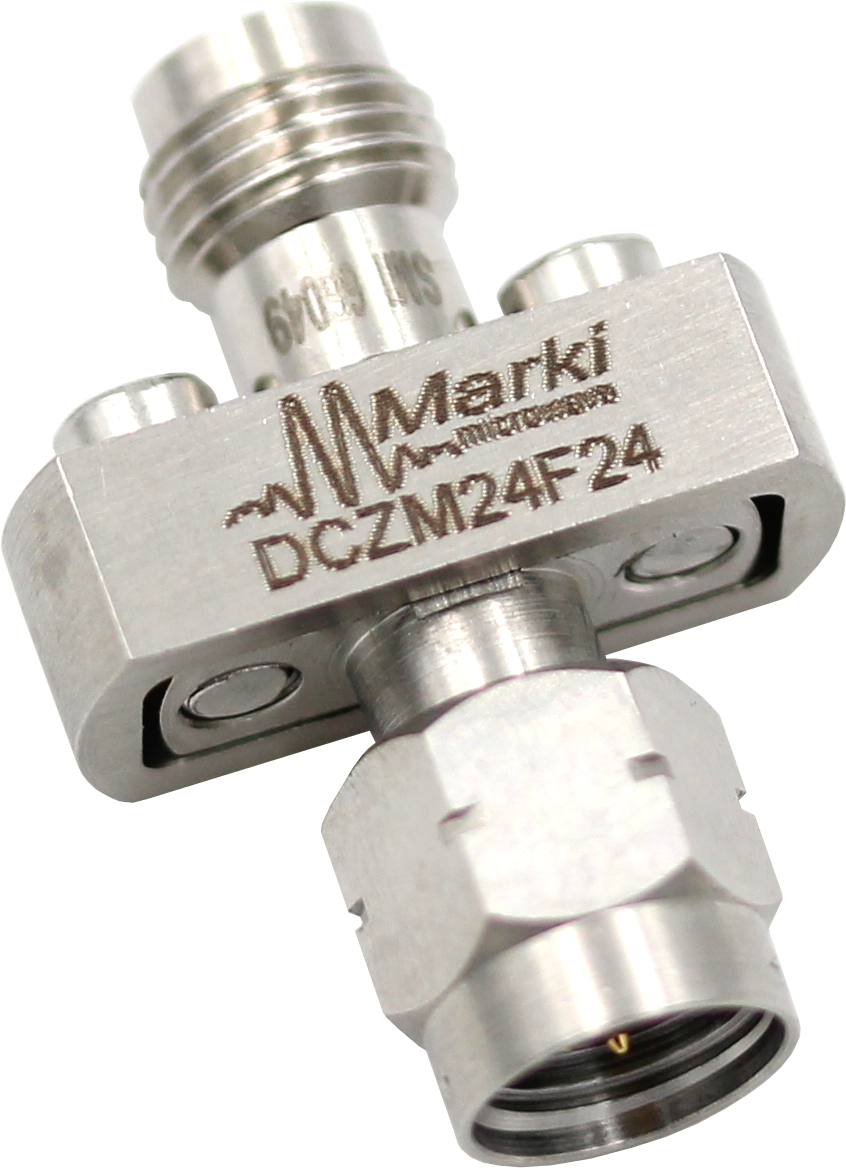
DCZM24F24
DC-Block
These DC blocks feature resonance-free operation and provide superior return loss and insertion loss across very broad bandwidths.

| Parameter | Typ | Unit |
|---|---|---|
| Frequency Range | 0.000004 to 50 | GHz |
| Capacitance | 1 | μF |
| Insertion Loss | 0.7 | dB |
Summary only – refer to the Electrical Specifications, Absolute Maximum Ratings, and Recommended Operating Range tables for complete details.
| Part Number | Description | Connectors | Green Status | Product Lifecycle | Export Classification |
|---|---|---|---|---|---|
| DCZM24F24 | DC-Block | - | Consult Factory | Released | EAR99 |
| DCZM24M24 | DC-Block | Standard | Consult Factory | Released | EAR99 |
| DCZF24F24 | DC-Block | Standard | Consult Factory | Released | EAR99 |

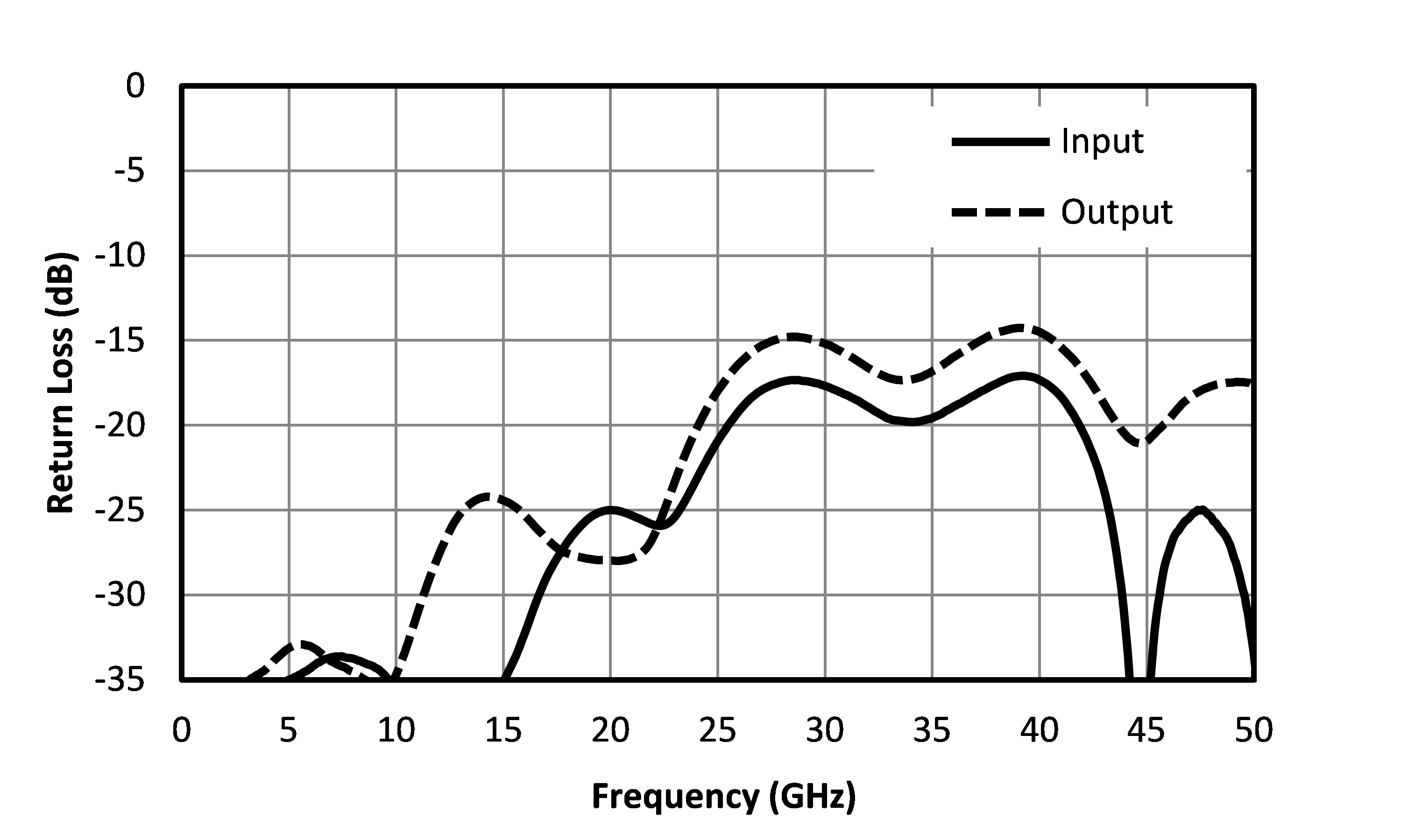
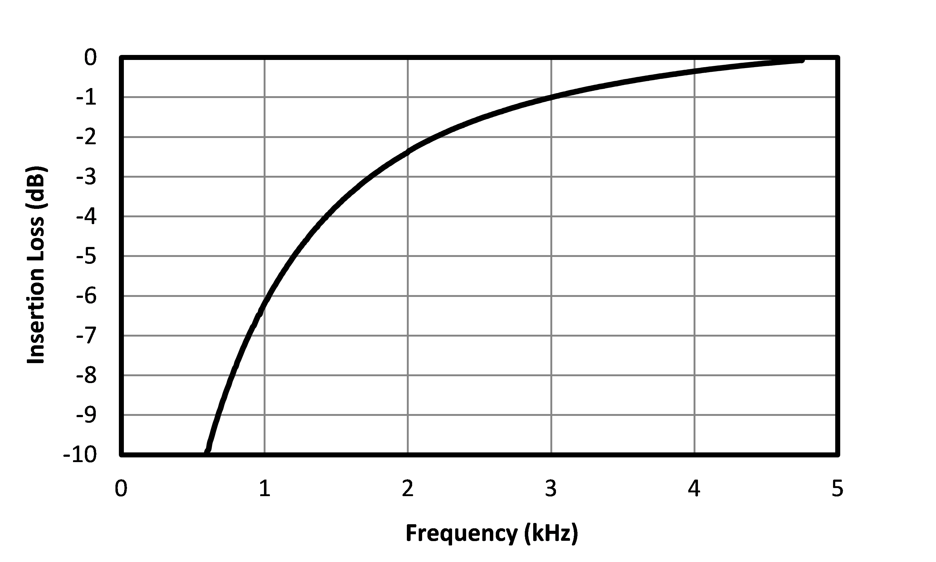
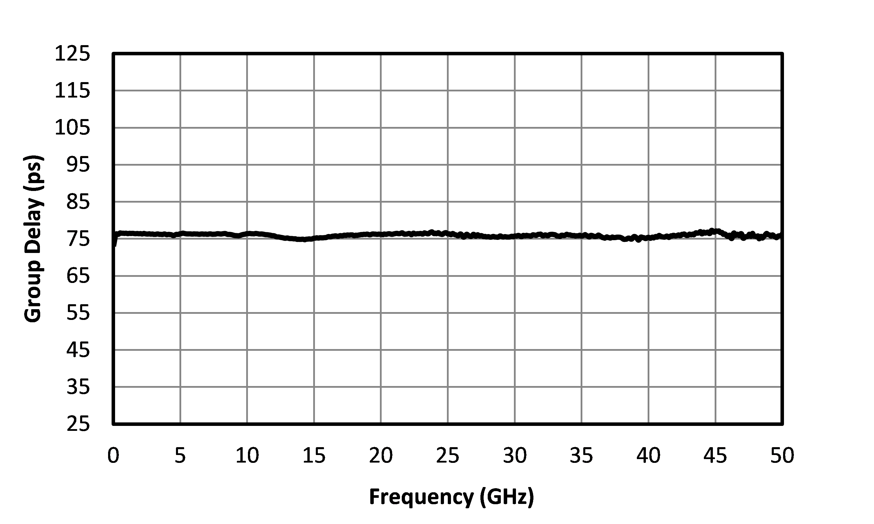
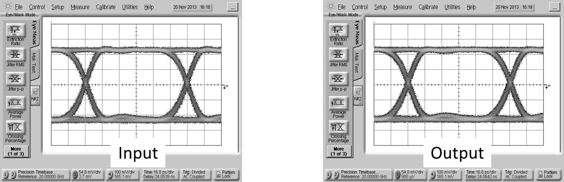
Eye diagrams are taken with a 2³¹-1 P PRBS input demonstrating minimal eye distortion/closure.
| Parameter | Test Conditions | Minimum Frequency (GHz) | Maximum Frequency (GHz) | Min | Typ | Max | Unit |
|---|---|---|---|---|---|---|---|
| Frequency Range | - | 0.000004 | 50 | - | - | - | GHz |
| Capacitance | - | 0 | 50 | - | 1 | - | μF |
| Group Delay | - | 0 | 50 | - | 75 | - | ps |
| Insertion Loss | - | 0 | 50 | - | 0.7 | 1.25 | dB |
| Near DC Insertion Loss | - | 0 | 0 | - | 3 | - | dB |
| Rise Time 1 | - | 0 | 50 | - | 6 | - | ps |
| VSWR | - | 0 | 50 | - | 1.4 | - | - |
[1] Specified as 90%/10%. Calculated from τ_balun² = (τ_out² – τ_in²) with a 10 Gb/s input pattern.
| Parameter | Maximum Rating | Unit |
|---|---|---|
| DC Voltage | 16 | V |
| RF Power Handling, Average | 1 | W |
| Port | Function | Connector Type | Description | DC Equivalent Circuit |
|---|---|---|---|---|
| In/Out 1 | Input/Output | 2.4M | RF Input/Output port 1 of the device. Device is passive and reciprocal from port 1 to port 2. Ground is not isolated between ports 1 and 2. | - |
| In/Out 2 | Input/Output | 2.4F | RF Input/Output port 2 of the device. Device is passive and reciprocal from port 1 to port 2. Ground is not isolated between ports 1 and 2. | - |
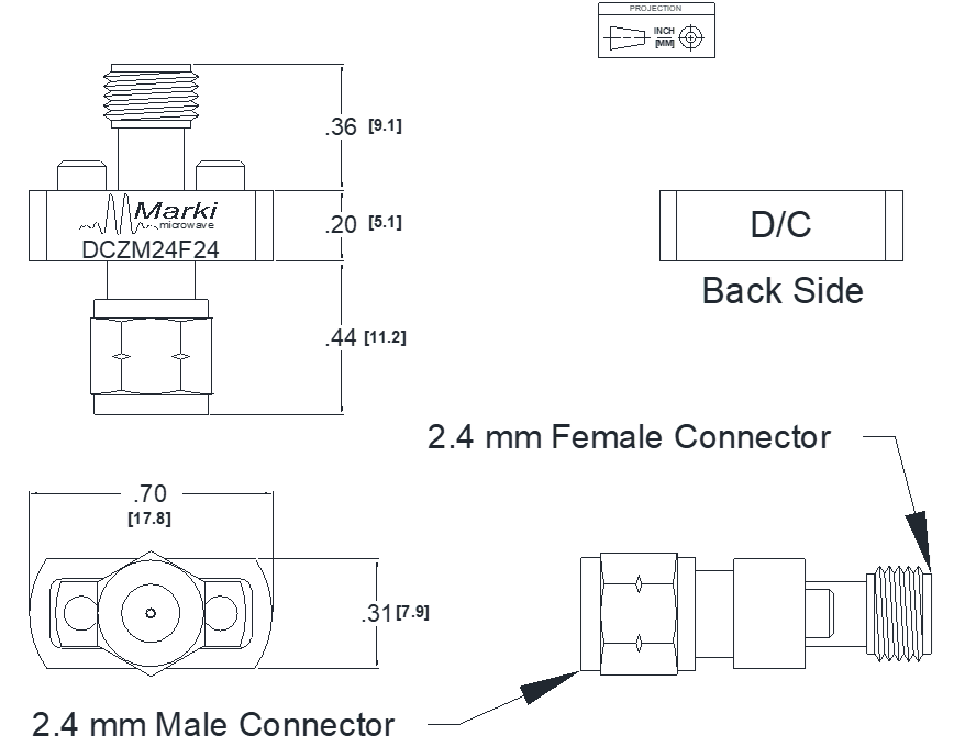
Download : Outline 2D Drawing
| Revision Code | Revision Date | Comment |
|---|---|---|
| - | 2023-06-13 | Initial Release |
MARKI MICROWAVE, LLC., (“MARKI”) PROVIDES TECHNICAL SPECIFICATIONS AND DATA (INCLUDING DATASHEETS), APPLICATION OR OTHER DESIGN ADVICE, WEB TOOLS, AND OTHER INFORMATION AND RESOURCES “AS IS” AND WITH ALL FAULTS. MARKI DISCLAIMS ALL WARRANTIES, EXPRESS OR IMPLIED, INCLUDING, WITHOUT LIMITATION, ANY IMPLIED WARRANTIES OF MERCHANTABILITY, FITNESS FOR A PARTICULAR PURPOSE, OR NON-INFRINGEMENT.
These resources are intended for developers skilled in the art designing with Marki products. You are solely responsible for (1) selecting the appropriate products for your application, (2) designing, validating, and testing your application, and (3) ensuring your application meets applicable standards and other requirements. Marki makes no guarantee regarding the suitability of its products for any particular purpose, nor does Marki assume any liability whatsoever arising out of your use or application of any Marki product.
Marki grants you permission to use these resources only for development of an application that uses Marki products. Other reproduction or use of these resources is strictly prohibited. No license is granted to any other Marki intellectual property or to any third-party intellectual property. Marki reserves the right to make changes to the product(s) or information contained herein without notice.
MARKI MICROWAVE, M wave logo, FastSwitch, and T3 MIXER are trademarks or registered trademarks of Marki Microwave, LLC. All other trademarks used are the property of their respective owners.
© 2023, Marki Microwave, LLC