Rev: C | Copyright © 2020 Marki Microwave LLC.

General Description

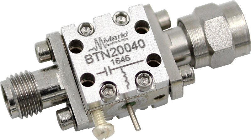
The BTN2-0040 is constructed using a custom-made, resonance-free conical inductor to achieve extremely broadband performance. By minimizing the overall inductor size and using proprietary packaging techniques, the BTN2-0040 is a superior option in terms of performance, reliability and ease-of-use when compared to cumbersome user-designed bias tees employing off-the-shelf conical inductors. The extremely low cutoff and resonance free operation makes the BTN2-0040 suitable for biasing amplifiers, lasers, and modulators driven with high frequency data patterns.

Features

  • Broadband: 3 MHz to 40 GHz
  • Low Insertion Loss
  • High Power
  • Non-Resonant
  • Compact Size

Functional Block Diagram

Block Diagram

Electrical Performance Summary

ParameterTypUnit
Frequency Range0.003 to 40GHz
DC Current 2A
DC Voltage 50V
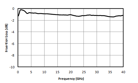
Insertion Loss 1.5dB
DC Port Isolation 50dB

Summary only – refer to the Electrical Specifications, Absolute Maximum Ratings, and Recommended Operating Range tables for complete details.

Part Ordering Options

Part NumberDescriptionConnectorsGreen StatusProduct LifecycleExport Classification
BTN2-0040High Power Bias TeeStandard

REACH

RoHS

ReleasedEAR99

Table Of Contents

Typical Performance

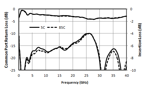
RF insertion loss (dB) graph for BTN2-0040
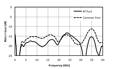
RFC Return Loss vs Temperature graph for BTN2-0040
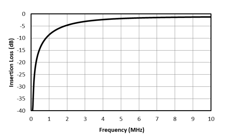
Low frequency RF response graph for BTN2-0040
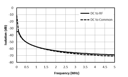
Low frequency isolation graph for BTN2-0040
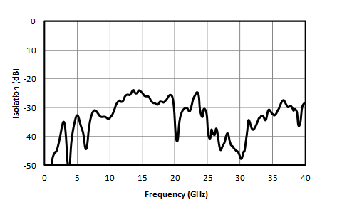
DC-RF isolation graph for BTN2-0040
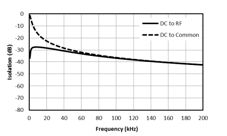
Near DC isolation graph for BTN2-0040
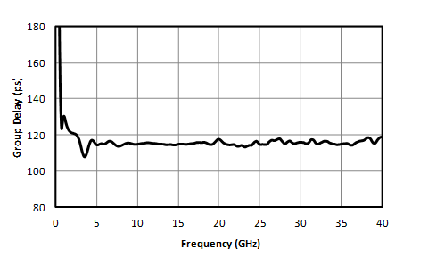
Group Delay graph for BTN2-0040
Performance over temperature graph for BTN2-0040

Typical Performance vs Bias Current at Low frequencies

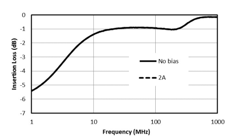
Insertion Loss vs Bias Current graph for BTN2-0040
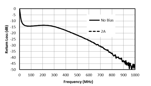
Common Return Loss vs Bias Current graph for BTN2-0040
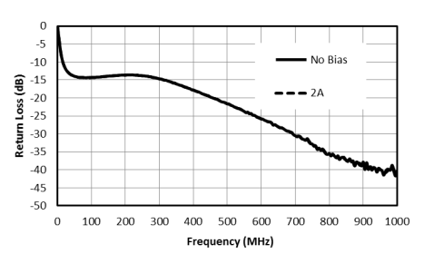
RF Return Loss vs Bias Current graph for BTN2-0040

Time Domain Plots

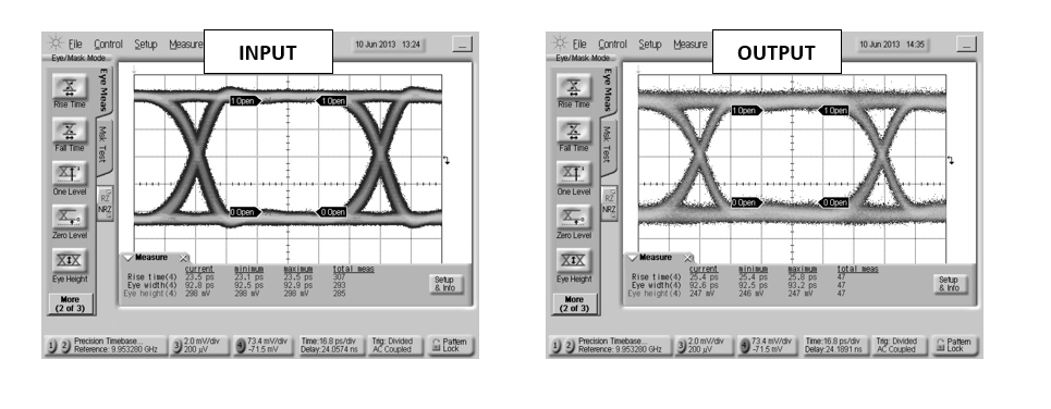
Oscilloscope measurements of the BTN2-0040 with a 10Gb/s PRBS pattern. Eye diagrams are taken with a 231-1 PRBS input demonstrating minimal eye distortion/closure afforded by the extremely low frequency operation of the bias tee.

.  Oscilloscope measurements of the BTN2-0040 with a 10Gb/s PRBS pattern. Eye diagrams are taken with a 231-1 PRBS input demonstrating minimal eye distortion/closure afforded by the extremely low frequency operation of the bias tee.  graph for BTN2-0040

Specifications

Electrical Specifications

Specifications guaranteed at +25C, measured in a 50-Ohm system

ParameterTest ConditionsMinimum
Frequency
(GHz)
Maximum
Frequency
(GHz)
MinTypMaxUnit
Frequency Range-0.003 40---GHz
Capacitance -- --100-nF
DC Port Isolation -0.003 1-50-dB
DC Port Isolation -1 40-30-dB
DC Resistance -- --0.3-Ω
Inductance -- --4.7-μH
Insertion Loss -0.003 0.1-2-dB
Insertion Loss -0.01 40-1.52.2dB
Return Loss -0.003 40-13-dB
Risetime/Falltime 1-- --10-ps

[1] 𝜏bt2 = (𝜏out2 - 𝜏in2)

Absolute Maximum Ratings

ParameterMaximum RatingUnit
DC Current 2A
DC Voltage 50V
Maximum Storage Temperature 125°C
Minimum Storage Temperature -65°C
RF Power Handling 10W
Minimum Operating Temperature -55°C
Maximum Operating Temperature 100°C

Package Information

ParameterDetailsRating
Weight-10g
Dimensions-11.94 x 11.94 mm

Port Configuration and Functions

Port Functions

PortFunctionConnector TypeDescriptionDC Equivalent
Circuit
CommonRF+DC 2.92MThis port is DC blocked to the RF port and DC connected to the DC port trough an internal RF chokeEquivalent circuit for the RF+DC
DCDC -This port is internally connected to an RF choke which is DC connected to the RF+DC port and DC blocked to the RF port.Equivalent circuit for the DC
RFRF 2.92FThis port is internally DC blocked to the RF+DC and DC ports.Equivalent circuit for the RF

Operation

Application Information

Bt N2 0040 App Ckt

Example Schematics of a) Broadband Microwave Amplifier Biasing, b) Laser/LED Biasing for Data Communication and c) Mach-Zender Modulator Biasing for Data Communication

Mechanical Data

Outline Drawing

Download : Outline 2D Drawing Outline 3D Drawing Outline 3D STP

Outline Drawing

Revision History

Revision CodeRevision DateComment
C2020-10-01Added Performance plots vs Bias Current

DISCLAIMER

MARKI MICROWAVE, LLC., (“MARKI”) PROVIDES TECHNICAL SPECIFICATIONS AND DATA (INCLUDING DATASHEETS), APPLICATION OR OTHER DESIGN ADVICE, WEB TOOLS, AND OTHER INFORMATION AND RESOURCES “AS IS” AND WITH ALL FAULTS. MARKI DISCLAIMS ALL WARRANTIES, EXPRESS OR IMPLIED, INCLUDING, WITHOUT LIMITATION, ANY IMPLIED WARRANTIES OF MERCHANTABILITY, FITNESS FOR A PARTICULAR PURPOSE, OR NON-INFRINGEMENT.

These resources are intended for developers skilled in the art designing with Marki products. You are solely responsible for (1) selecting the appropriate products for your application, (2) designing, validating, and testing your application, and (3) ensuring your application meets applicable standards and other requirements. Marki makes no guarantee regarding the suitability of its products for any particular purpose, nor does Marki assume any liability whatsoever arising out of your use or application of any Marki product.

Marki grants you permission to use these resources only for development of an application that uses Marki products. Other reproduction or use of these resources is strictly prohibited. No license is granted to any other Marki intellectual property or to any third-party intellectual property. Marki reserves the right to make changes to the product(s) or information contained herein without notice.

MARKI MICROWAVE, M wave logo, FastSwitch, and T3 MIXER are trademarks or registered trademarks of Marki Microwave, LLC. All other trademarks used are the property of their respective owners.

© 2020, Marki Microwave, LLC