Port Diagram
A top-down view of the EBAL-0050 package outline drawing is shown below. Marki baluns are passive reciprocal devices allowing either single ended to differential or differential to single ended conversion.

Sales: 408-778-9952 | General: 408-778-4200 | Fax: 408-778-4300
Sales & Customer Support: [email protected]
Tech Support: [email protected]
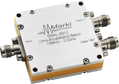
The EBAL-0050 is an ultra-broadband 2:1 balun (unbalanced to balanced transformer), hand-tuned for optimal amplitude and phase balance. The EBAL-0050 transforms between a 50Ω common input and a 100Ω differential output. It operates over a 10 MHz to 50 GHz bandwidth, with typical 0.25 dB amplitude and 2° phase balance, low 4 dB insertion loss as a mode converter. The EBAL-0050 can be used for performing measurements on high frequency differential devices, including cables, microchips, and communication systems. It is an excellent choice for test & measurement benches, high speed analog-to-digital converters, balanced receivers, baseband digital modulations, and signal integrity. For accurate simulations, use the provided S3P file taken from measured production units. The EBAL-0050 is in a 1.5 x 1.5 inch connectorized package and features 2.40 mm Female connectors on the common input and differential output ports.
N/A

| Part Number | Description | Connectors | Green Status | Product Lifecycle | Export Classification |
|---|---|---|---|---|---|
| EBAL-0050 | 10 MHz to 50 GHz Broadband Balun | Standard | REACH RoHS | Released | EAR99 |
| Part Number | Description | Connectors | Green Status | Product Lifecycle | Export Classification |
|---|---|---|---|---|---|
| EBAL-0050 | 10 MHz to 50 GHz Broadband Balun | Standard | REACH RoHS | Released | EAR99 |
EBAL-0050
10 MHz to 50 GHz Broadband Balun
| Revision Code | Revision Date | Comment |
|---|---|---|
| - | 2023-06-01 | Datasheet Initial Release |
EBAL-0050
10 MHz to 50 GHz Broadband Balun
A top-down view of the EBAL-0050 package outline drawing is shown below. Marki baluns are passive reciprocal devices allowing either single ended to differential or differential to single ended conversion.
| Port | Function | Connector Type | Description | DC Equivalent Circuit |
|---|---|---|---|---|
| Data 0° | D+ / 0° Port (Balanced) | 2.4F | The 0° port is DC short to the 180° port and DC open to ground and common. |  |
| Data 180° | D- / 180° Port (Balanced) | 2.4F | The 180° port is DC short to the 0° port and DC open to ground and common. | |
| Input | Common Port / SE (Unbalanced) | 2.4F | The common port is DC short to ground. |  |
EBAL-0050
10 MHz to 50 GHz Broadband Balun
The Absolute Maximum Ratings indicate limits beyond which damage may occur to the device. If these limits are exceeded, the device may be inoperable or have a reduced lifetime.
| Parameter | Maximum Rating | Unit |
|---|---|---|
| Maximum Operating Temperature | 100 | °C |
| Maximum Storage Temperature | 125 | °C |
| Minimum Operating Temperature | -55 | °C |
| Minimum Storage Temperature | -65 | °C |
| Parameter | Details | Rating |
|---|---|---|
| ESD | 250 to < 500 Volts | HBM Class 1A |
| Dimensions | - | 38.10x38.10 mm |
EBAL-0050
10 MHz to 50 GHz Broadband Balun
The electrical specifications apply at TA=+25°C in a 50Ω system. Min and Max limits are guaranteed at TA=+25°C.
| Parameter | Test Conditions | Minimum Frequency (GHz) | Maximum Frequency (GHz) | Min | Typ | Max | Unit |
|---|---|---|---|---|---|---|---|
| Amplitude Balance | - | 0.01 | 40 | - | 0.25 | 1 | dB |
| Amplitude Balance | - | 40 | 50 | - | 0.5 | 1.5 | dB |
| Common Mode Rejection | - | 40 | 50 | 20 | 29 | - | dB |
| Common Mode Rejection | - | 0.01 | 40 | 25 | 33 | - | dB |
| Common Port Return Loss | - | 0.01 | 50 | - | 20 | - | dB |
| Insertion Loss as a Mode Converter | - | 0.01 | 50 | - | 4 | 8 | dB |
| Isolation | - | 0.01 | 50 | - | 5 | - | dB |
| Nominal Phase Shift | - | 0.01 | 50 | - | 180 | - | ° |
| Output Return Loss | - | 0.01 | 50 | - | 7 | - | dB |
| Phase Balance | - | 40 | 50 | - | 5 | 15 | dB |
| Phase Balance | - | 0.01 | 40 | - | 2 | 10 | ° |
| Impedance | - | - | - | - | 50 | - | Ω |
| Impedance Ratio | - | - | - | - | 2:1 | - | - |
EBAL-0050
10 MHz to 50 GHz Broadband Balun
Mixed mode scattering parameters are used to characterize differential circuits. For baluns, this means that the 0° and 180° ports become a single 100Ω differential port and the common port remains the same 50Ω common port. The two-port s-parameters of the balun are then characterized based on differential (d), common mode (c), or single-ended (s) signals. For example: Sds21 is the differential output response given a single ended input.


EBAL-0050
10 MHz to 50 GHz Broadband Balun
Three port scattering parameters measured as three single-ended 50Ω ports showing relationship between any two ports.


EBAL-0050
10 MHz to 50 GHz Broadband Balun
