Absolute Maximum Ratings
| Parameter | Maximum Rating | Unit |
|---|---|---|
| RF Power Handling | 1 | W |
Sales: 408-778-9952 | General: 408-778-4200 | Fax: 408-778-4300
Sales & Customer Support: [email protected]
Tech Support: [email protected]
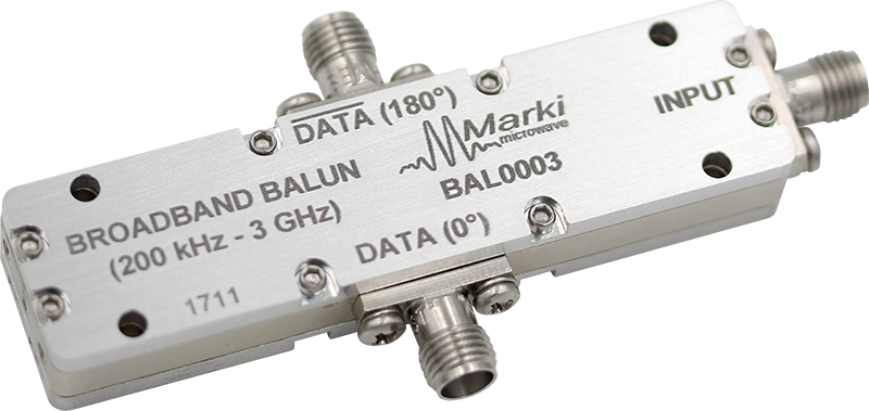
The BAL-0003SMG is a broadband surface mount balun, hand-tuned for optimal phase and amplitude balance over a 500 kHz to 3 GHz bandwidth. It serves as an excellent choice for analog to digital converters, balanced receivers, baseband digital modulations, and signal integrity enhancement.
| Part Number | Description | Connectors | Green Status | Product Lifecycle | Export Classification |
|---|---|---|---|---|---|
| BAL-0003 | BROADBAND BALUN (200 kHz to 3 GHz) | Standard | REACH RoHS | Released | EAR99 |
| Part Number | Description | Connectors | Green Status | Product Lifecycle | Export Classification |
|---|---|---|---|---|---|
| BAL-0003 | BROADBAND BALUN (200 kHz to 3 GHz) | Standard | REACH RoHS | Released | EAR99 |
BAL-0003
BROADBAND BALUN (200 kHz to 3 GHz)
| Revision Code | Revision Date | Comment |
|---|---|---|
| - | 2011-01-01 | Datasheet initial Release |
| A | 2014-01-01 | Typical Performance plots added |
| B | 2019-10-01 | Mixed Mode Scattering Parameters added |
| C | 2019-11-01 | RoHs Compliant assembly |
| D | 2020-07-01 | Specs Table Update |
| E | 2020-10-01 | Specs Table Update |
BAL-0003
BROADBAND BALUN (200 kHz to 3 GHz)
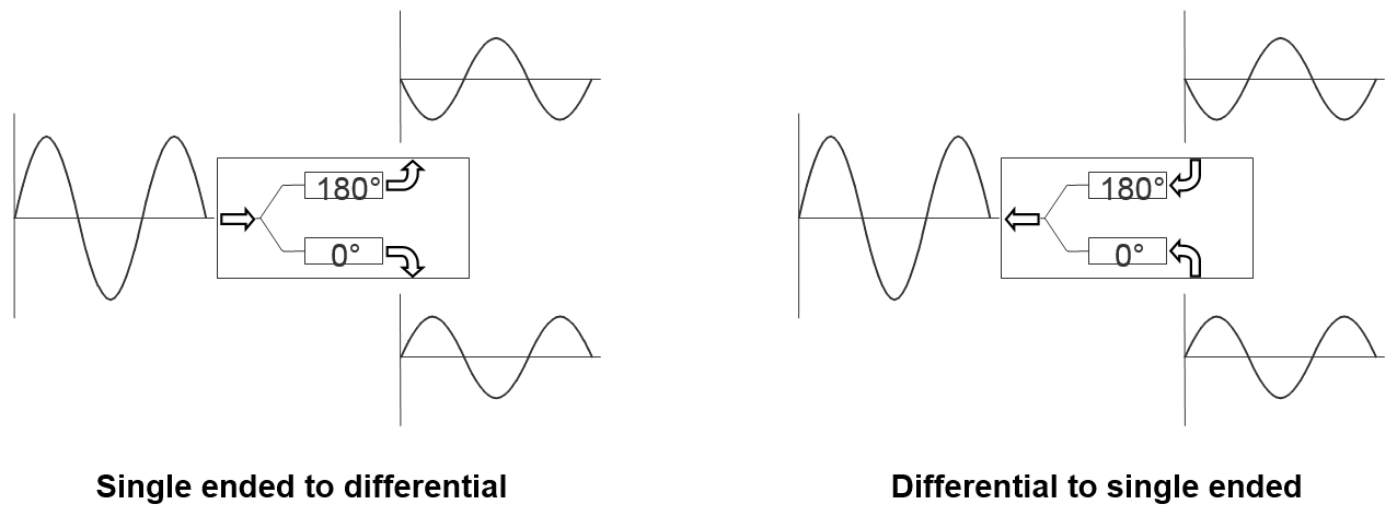
| Port | Function | Connector Type | Description | DC Equivalent Circuit |
|---|---|---|---|---|
| Common Port / In (Unbalanced) | RF Input | SMAF | The common port is DC short to ground. |  |
| Out 1 / 0° Port (Balanced) | 0° Port | SMAF | The 0o port is DC short to ground. |  |
| Out 2/ 180° Port | 180° Port | SMAF | The 180o port is DC short to ground. | |
BAL-0003
BROADBAND BALUN (200 kHz to 3 GHz)
| Parameter | Maximum Rating | Unit |
|---|---|---|
| RF Power Handling | 1 | W |
| Parameter | Details | Rating |
|---|---|---|
| Weight | - | 26g |
| Dimensions | - | 66.04 x 16.76 mm |
BAL-0003
BROADBAND BALUN (200 kHz to 3 GHz)
Specifications guaranteed from -55 to +100°C, measured in a 50Ω system.
| Parameter | Test Conditions | Minimum Frequency (GHz) | Maximum Frequency (GHz) | Min | Typ | Max | Unit |
|---|---|---|---|---|---|---|---|
| Amplitude Balance | - | 0.0002 | 3 | - | 0.05 | 0.5 | dB |
| Common Mode Rejection | - | 0.0002 | 3 | 35 | 45 | - | dB |
| Impedance Ratio | - | - | - | - | 2:1 | - | - |
| Insertion Loss as a Mode Converter | - | 0.0002 | 3 | - | 4 | 5 | dB |
| Isolation | - | 0.0002 | 3 | - | 8 | - | dB |
| Nominal Phase Shift | - | 0.0002 | 3 | - | 180 | - | ° |
| Phase Balance | - | 0.0002 | 3 | - | 1 | 5 | ° |
| Risetime/Falltime 1 | - | 0.0002 | 3 | - | 48 | - | ps |
| VSWR (Input) | - | 0.0002 | 3 | - | 8 | - | - |
| VSWR (Output) | - | 0.0002 | 3 | - | 1.7 | - | - |
[1] Specified as 90%/10%. Calculated from Tau_balun2 = (Tau_out2 – Tau_in2)
BAL-0003
BROADBAND BALUN (200 kHz to 3 GHz)
Oscilloscope measurements of the BAL-0003 with a 2.5 Gb/s PBRS pattern. Bit pattern is measured with a 27-1 PBRS input demonstrating extremely good pulse fidelity for both inverted and non-inverted output. Eye diagrams are taken with 231-1 PBRS input demonstrating minimal eye distortion/closure afforded by the extremely low frequency operation of the balun (<200 kHz).

BAL-0003
BROADBAND BALUN (200 kHz to 3 GHz)
Three port scattering parameters measured as three single-ended 50Ω ports showing relationship between any two ports. For example: S21 and S31, often referred to as insertion loss of a balun, is the output response on ports 2 and 3 with an input stimulus on port 1.


BAL-0003
BROADBAND BALUN (200 kHz to 3 GHz)

BAL-0003
BROADBAND BALUN (200 kHz to 3 GHz)
Mixed mode scattering parameters are used to characterize differential circuits. For baluns, this means that the 0° and 180° ports become a single 100Ω differential port and the common port remains the same 50Ω common port. The two-port s-parameters of the balun are then characterized based on differential (d), common mode (c), or single-ended (s) signals. For example: S12ds is the differential output response given a single ended input.


BAL-0003
BROADBAND BALUN (200 kHz to 3 GHz)


BAL-0003
BROADBAND BALUN (200 kHz to 3 GHz)