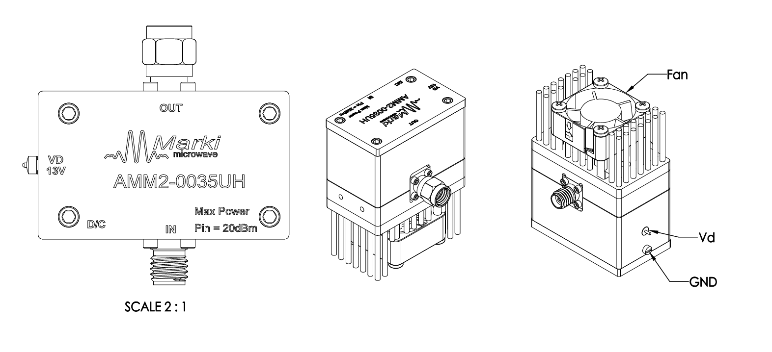
Port Diagram
The port diagram of the AMM2-0035UH is shown below.

Sales: 408-778-9952 | General: 408-778-4200 | Fax: 408-778-4300
Sales & Customer Support: [email protected]
Tech Support: [email protected]
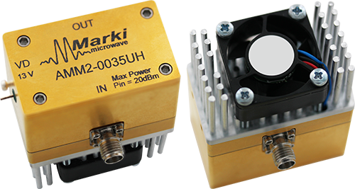
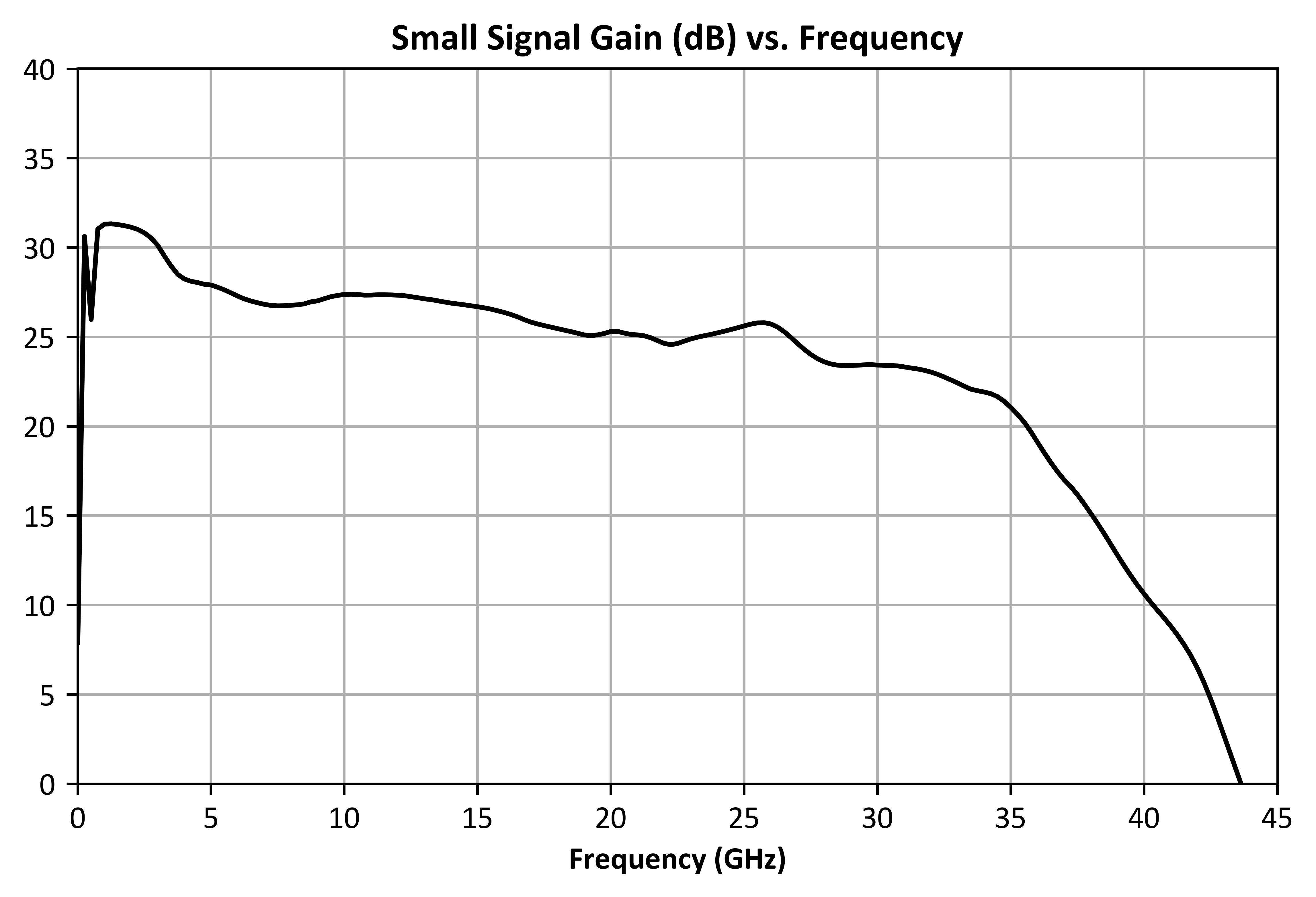
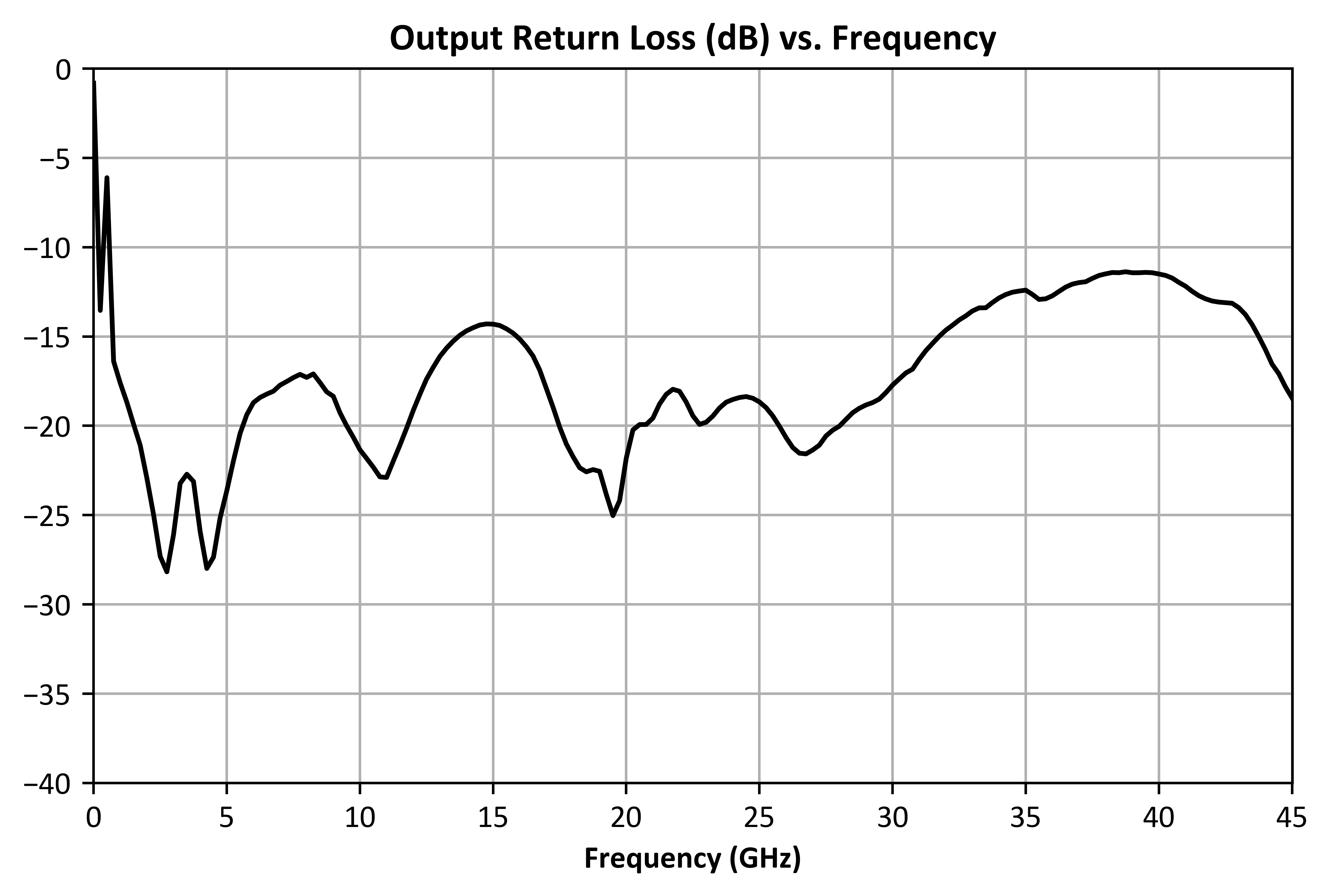
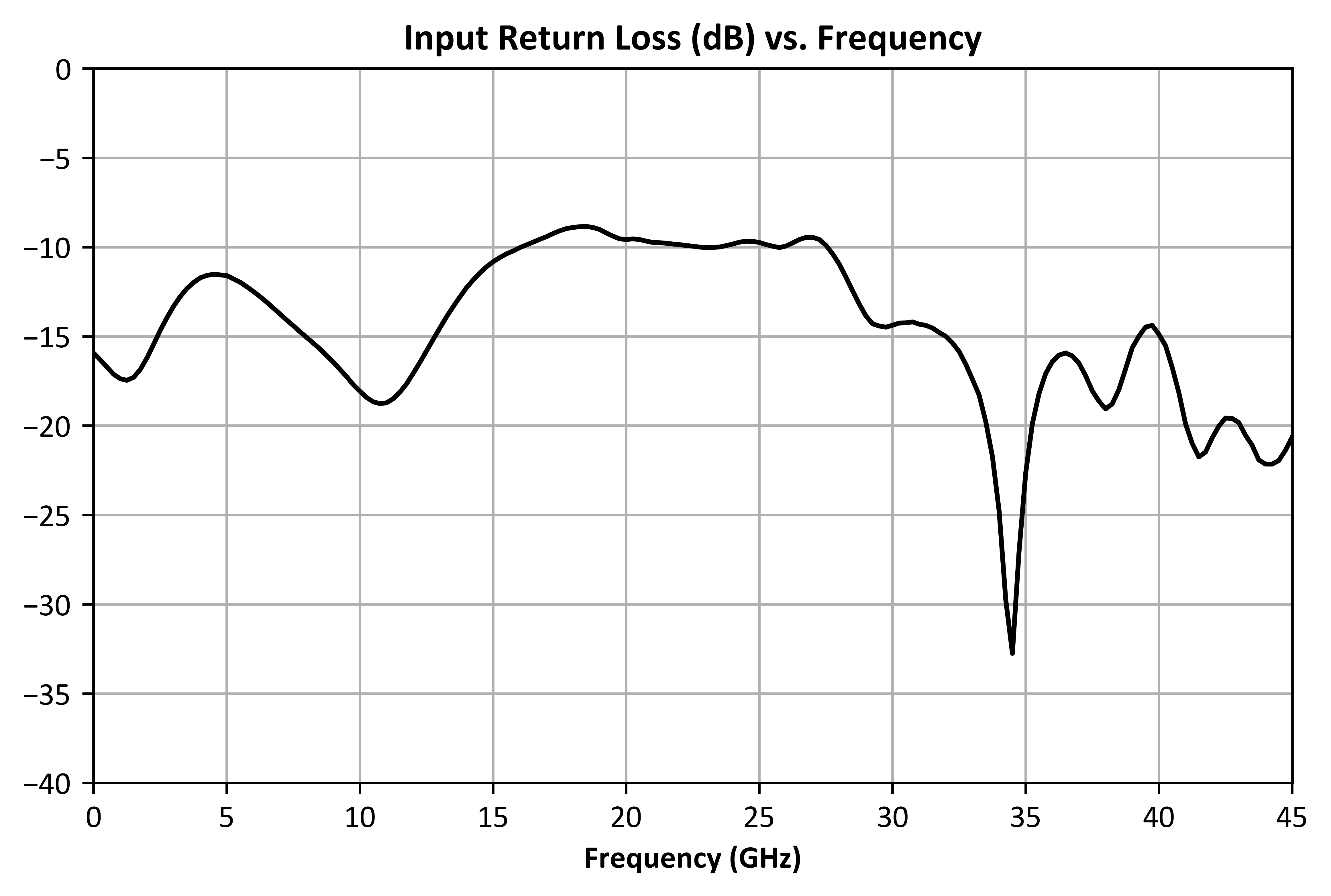
The AMM2-0035UH is a high gain, medium power broadband amplifier enabling operation over a 500 MHz to 35 GHz frequency range. Delivering +27 dBm saturated output power up to 15 GHz, 26 dB typical gain and excellent return losses, the AMM2-0035UH eliminates the need for multiple gain stages across wideband systems. This amplifier is housed in a 1” x 1.7” connectorized module and operates with a single positive bias supply without the need for sequencing.

| Part Number | Description | Package | Connectors | Green Status | Product Lifecycle | Export Classification |
|---|---|---|---|---|---|---|
| AMM2-0035UH | 500 MHz to 35 GHz, Broadband High Gain, 1/2 Watt Distributed Amplifier | UH | - | REACH RoHS | Released | EAR99 |
| Part Number | Description | Package | Connectors | Green Status | Product Lifecycle | Export Classification |
|---|---|---|---|---|---|---|
| AMM2-0035UH | 500 MHz to 35 GHz, Broadband High Gain, 1/2 Watt Distributed Amplifier | UH | - | REACH RoHS | Released | EAR99 |
AMM2-0035UH
500 MHz to 35 GHz, Broadband High Gain, 1/2 Watt Distributed Amplifier
| Revision Code | Revision Date | Comment |
|---|---|---|
| - | 2026-11-04 | Initial Release |
AMM2-0035UH
500 MHz to 35 GHz, Broadband High Gain, 1/2 Watt Distributed Amplifier
The port diagram of the AMM2-0035UH is shown below.
| Port | Function | Connector Type | Description | DC Equivalent Circuit |
|---|---|---|---|---|
| GND | Ground | - | Ground Connection for UH Module |  |
| RF In | RF Input | 2.92F | RF input port to the module. This port is internally DC blocked and matched to 50 Ohms. | 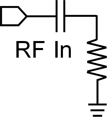 |
| RF Out | RF Output | 2.92M | RF output port to module. This port is internally DC blocked and matched to 50 Ohms. | 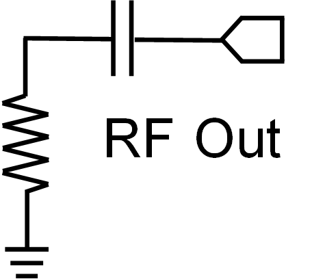 |
| Vd | Positive DC Supply Voltage | - | This pin provides DC power to the amplifier. DC voltage at this pin should be set to 13V for normal operation. | - |
AMM2-0035UH
500 MHz to 35 GHz, Broadband High Gain, 1/2 Watt Distributed Amplifier
The Absolute Maximum Ratings indicate limits beyond which damage may occur to the device. If these limits are exceeded, the device may become inoperable or have a reduced lifetime. Reliability limits are individual, instantaneous catastrophic limits only. Functional operation limits are indicated below. Operation of the device at multiple absolute maximum limits or for extended periods at a single limit can cause degradation and damage to the device.
| Parameter | Maximum Rating | Unit |
|---|---|---|
| Maximum Operating Temperature for MTTF > 1E6 hours | 65 | °C |
| Maximum Storage Temperature | 125 | °C |
| Minimum Operating Temperature for MTTF > 1E6 hours | -40 | °C |
| Minimum Storage Temperature | -65 | °C |
| Power Supply DC Voltage (Vd) | 13.5 | V |
| RF Input Power | 20 | dBm |
| Parameter | Details | Rating |
|---|---|---|
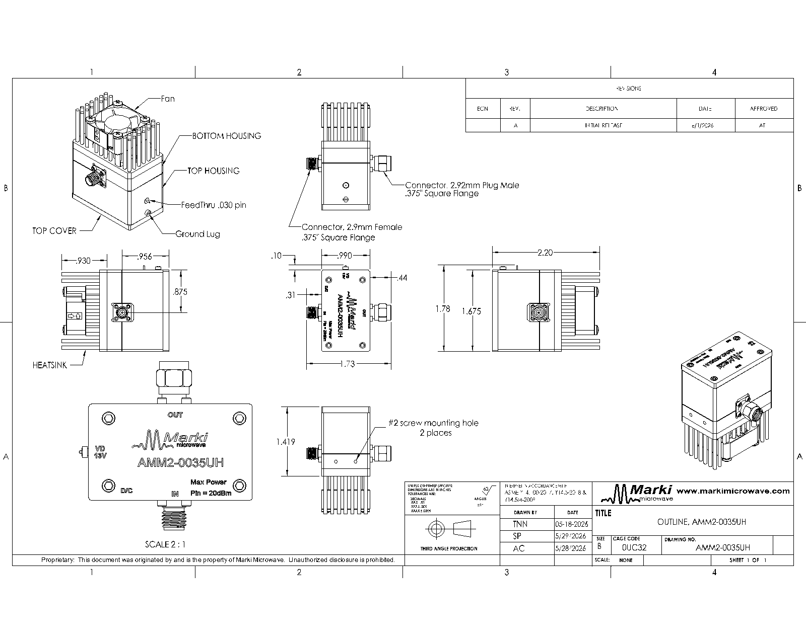
| Dimensions | - | 25.2 x 42.6 x 55.9 mm |
The Recommended Operating Conditions indicate the limits, inside which the device should be operated, to guarantee the performance given in Electrical Specifications. Operating outside these limits may not necessarily cause damage to the device, but the performance may degrade outside the limits of the Electrical Specifications. For limits, above which damage may occur, see Absolute Maximum Ratings.
| Parameter | Min | Nominal | Max | Unit |
|---|---|---|---|---|
| Power Supply DC Current (Ib) 1 | - | 445 | 500 | mA |
| Positive DC Bias Voltage (Vb) | - | 13 | - | V |
| Input Power for Saturation | - | 0 | - | dBm |
[1] Recommended operating current condition without RF input applied.
AMM2-0035UH
500 MHz to 35 GHz, Broadband High Gain, 1/2 Watt Distributed Amplifier
| Parameter | Test Conditions | Minimum Frequency (GHz) | Maximum Frequency (GHz) | Min | Typ | Max | Unit |
|---|---|---|---|---|---|---|---|
| Small Signal Gain | Vd=13V, Pin=-20dBm | 0.5 | 30 | - | 26 | - | dB |
| Input Return Loss | Vd=13V, Pin=-20dBm | 0.5 | 35 | - | 10 | - | dB |
| Output Return Loss | Vd=13V, Pin=-20dBm | 0.5 | 35 | - | 15 | - | dB |
| Reverse Isolation | Vd=13V, Pin=-20dBm | 0.5 | 35 | - | 70 | - | dB |
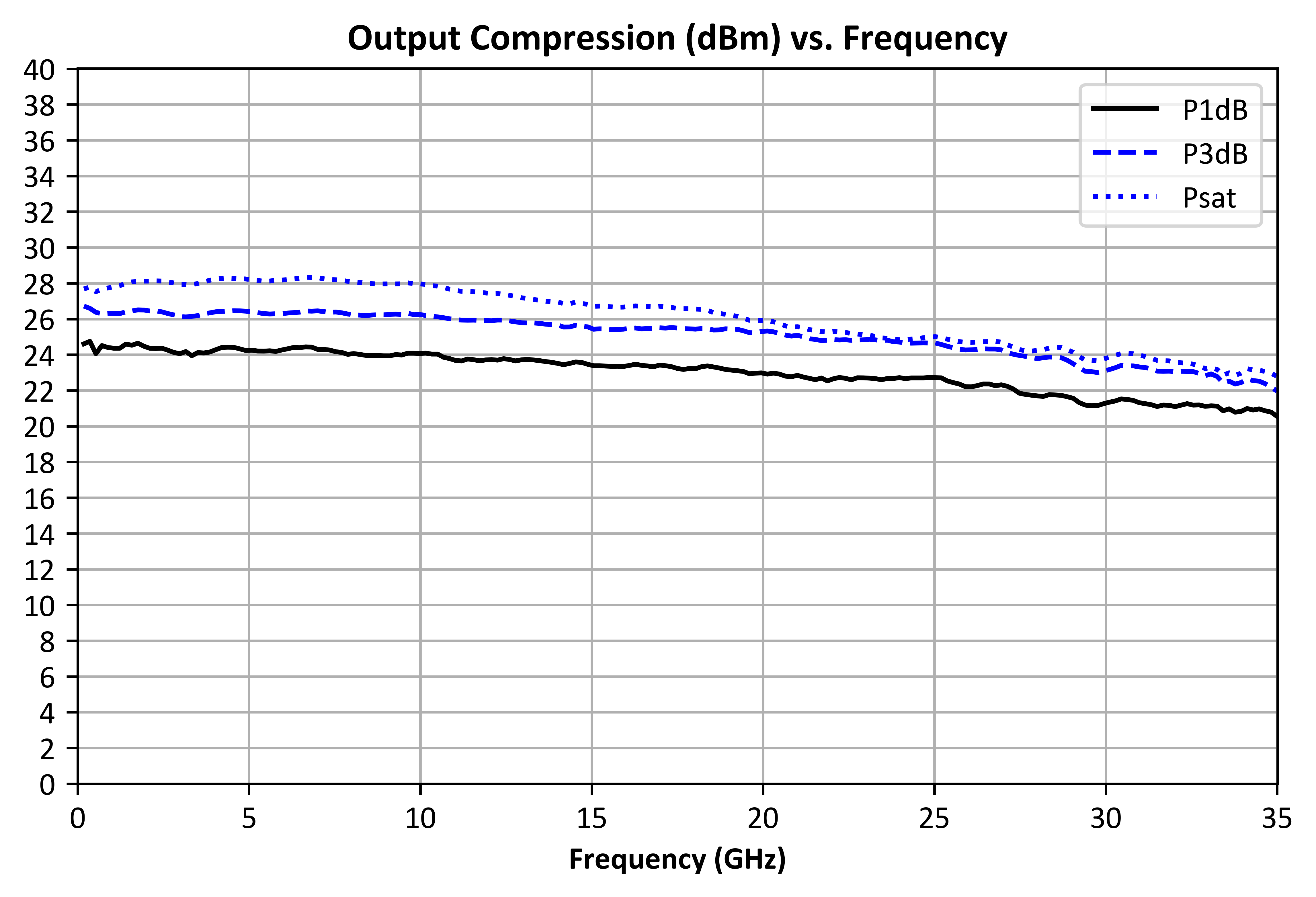
| Saturated Output Power | Vd=13V | 0.5 | 10 | - | 28 | - | dBm |
| Saturated Output Power | Vd=13V | 10 | 25 | - | 26 | - | dBm |
| Saturated Output Power | Vd=13V | 25 | 35 | - | 23 | - | dBm |
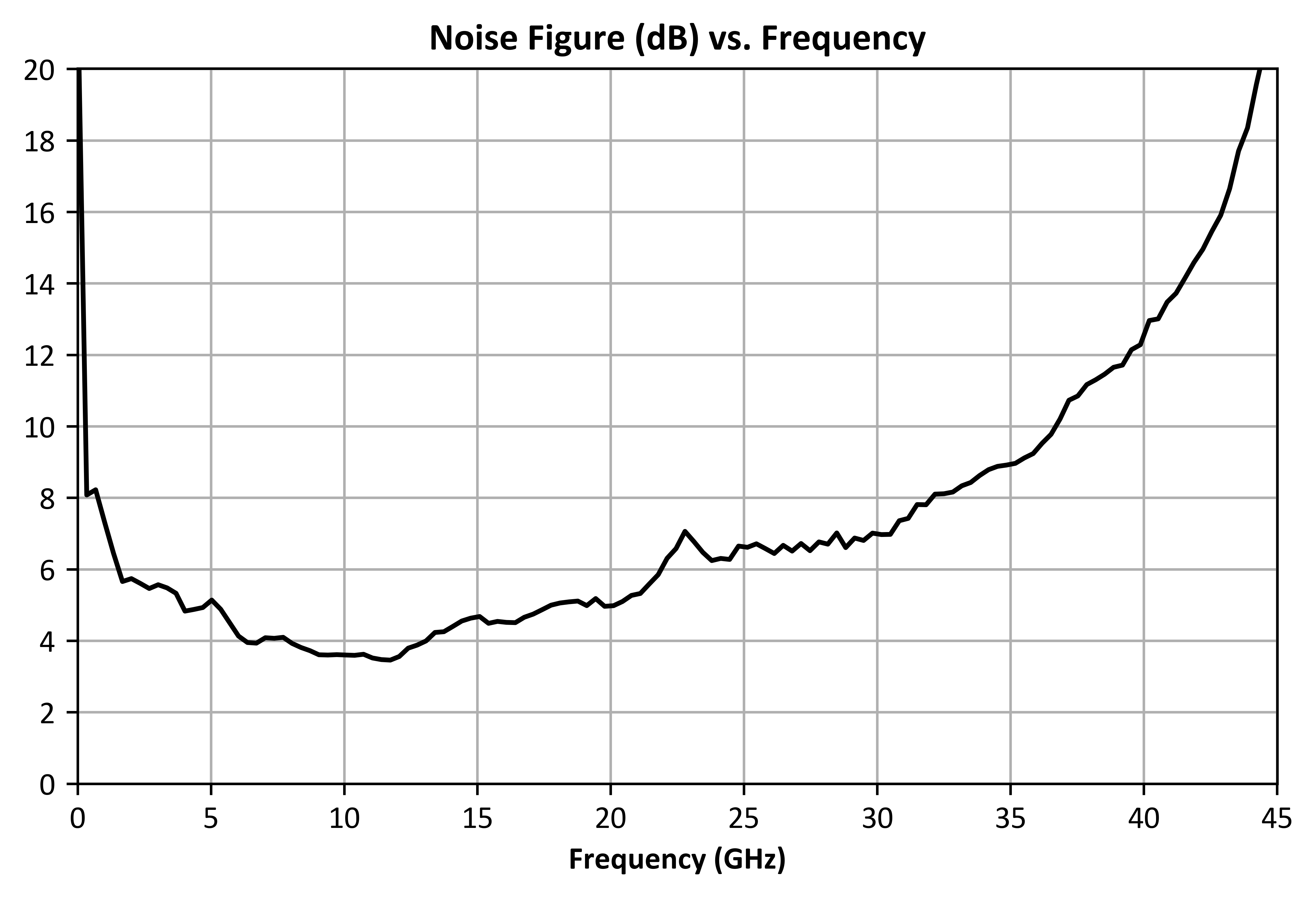
| Noise Figure | Vd=13V | 0.5 | 35 | - | 6 | - | dB |
| Output P1dB | Vd=13V, Pin=-20dBm | 0.5 | 10 | - | 24 | - | dBm |
| Output P1dB | Vd=13V | 10 | 25 | - | 23 | - | dBm |
| Output P1dB | Vd=13V | 25 | 35 | - | 23 | - | dBm |
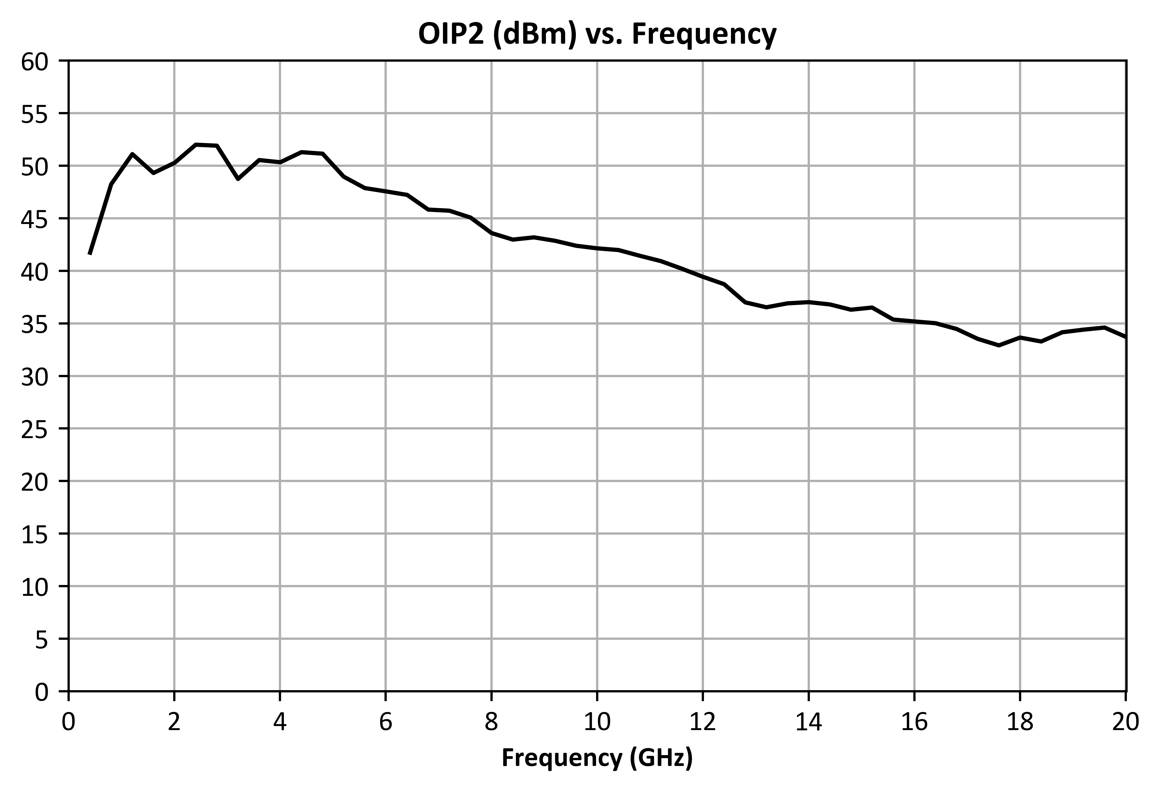
| Output IP2 | Vd=13V, Pin=-20dBm | 0.5 | 10 | - | 45 | - | dBm |
| Output IP2 | Vd=13V, Pin=-20dBm | 10 | 20 | - | 35 | - | dBm |
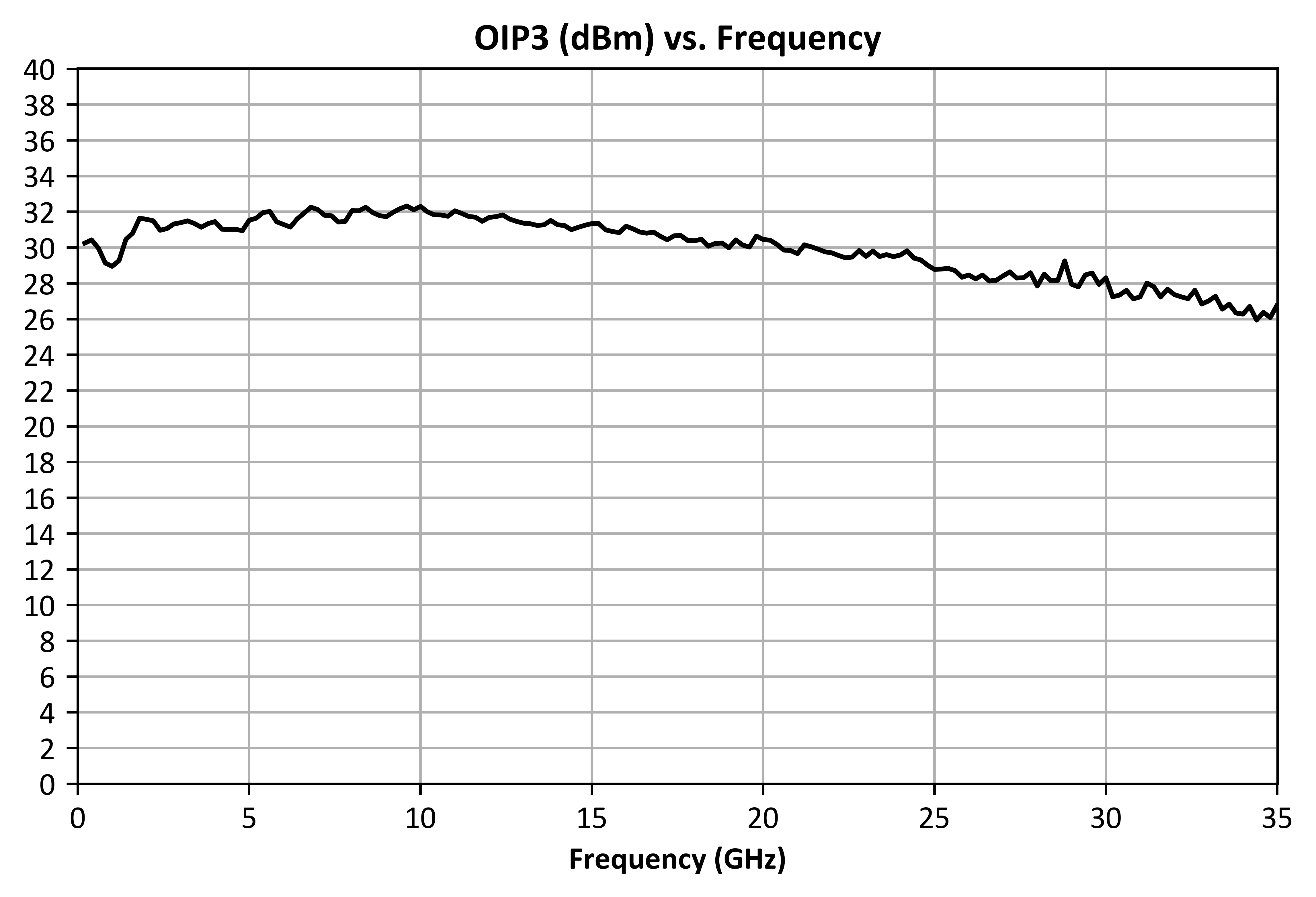
| Output IP3 | Vd=13V, Pin=-30dBm | 0.5 | 20 | - | 31 | - | dBm |
| Output IP3 | Vd=13V, Pin=-20dBm | 20 | 35 | - | 28 | - | dBm |
| Parameter | Test Conditions | Minimum Frequency (GHz) | Maximum Frequency (GHz) | Min | Typ | Max | Unit |
|---|---|---|---|---|---|---|---|
| Small Signal Gain | Vd=13V, Pin=-20dBm | 0.5 | 30 | - | 26 | - | dB |
| Input Return Loss | Vd=13V, Pin=-20dBm | 0.5 | 35 | - | 10 | - | dB |
| Output Return Loss | Vd=13V, Pin=-20dBm | 0.5 | 35 | - | 15 | - | dB |
| Reverse Isolation | Vd=13V, Pin=-20dBm | 0.5 | 35 | - | 70 | - | dB |
| Saturated Output Power | Vd=13V | 0.5 | 10 | - | 28 | - | dBm |
| Saturated Output Power | Vd=13V | 10 | 25 | - | 26 | - | dBm |
| Saturated Output Power | Vd=13V | 25 | 35 | - | 23 | - | dBm |
| Noise Figure | Vd=13V | 0.5 | 35 | - | 6 | - | dB |
| Output P1dB | Vd=13V, Pin=-20dBm | 0.5 | 10 | - | 24 | - | dBm |
| Output P1dB | Vd=13V | 10 | 25 | - | 23 | - | dBm |
| Output P1dB | Vd=13V | 25 | 35 | - | 23 | - | dBm |
| Output IP2 | Vd=13V, Pin=-20dBm | 0.5 | 10 | - | 45 | - | dBm |
| Output IP2 | Vd=13V, Pin=-20dBm | 10 | 20 | - | 35 | - | dBm |
| Output IP3 | Vd=13V, Pin=-30dBm | 0.5 | 20 | - | 31 | - | dBm |
| Output IP3 | Vd=13V, Pin=-20dBm | 20 | 35 | - | 28 | - | dBm |
AMM2-0035UH
500 MHz to 35 GHz, Broadband High Gain, 1/2 Watt Distributed Amplifier
AMM2-0035UH
500 MHz to 35 GHz, Broadband High Gain, 1/2 Watt Distributed Amplifier