Port Diagram
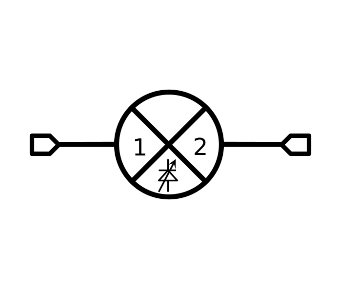
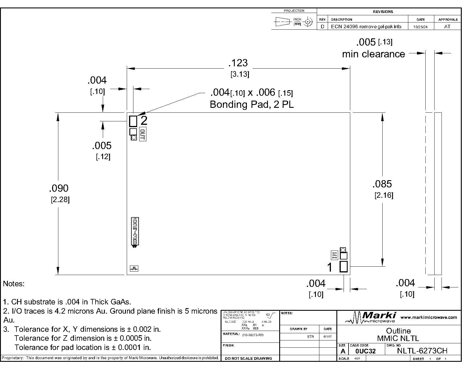
A top-down view of the NLTL-6273’s CH package outline drawing is shown below. The NLTL should only be used in the forward direction, with the input and output ports given in Port Functions.

Sales: 408-778-9952 | General: 408-778-4200 | Fax: 408-778-4300
Sales & Customer Support: [email protected]
Tech Support: [email protected]
NLTL-6273 is a MMIC non-linear transmission line (NLTL) based comb generator. This NLTL offers excellent phase noise performance over a low 0.7 to 5 GHz input frequency range with output tones beyond 40 GHz. NLTL-6273 is fabricated with GaAs Schottky diode based varactors on a 2.28 mm x 3.13 mm substrate. Both wire bondable die and connectorized modules are available.
| Part Number | Description | Package | Connectors | Green Status | Product Lifecycle | Export Classification |
|---|---|---|---|---|---|---|
| NLTL-6273S | GaAs MMIC Non-Linear Transmission Line | S | Standard | RoHS REACH | Released | EAR99 |
| NLTL-6273CH | GaAs MMIC Non-Linear Transmission Line | CH | - | RoHS REACH | Released | EAR99 |
| Part Number | Description | Package | Connectors | Green Status | Product Lifecycle | Export Classification |
|---|---|---|---|---|---|---|
| NLTL-6273S | GaAs MMIC Non-Linear Transmission Line | S | Standard | RoHS REACH | Released | EAR99 |
| NLTL-6273CH | GaAs MMIC Non-Linear Transmission Line | CH | - | RoHS REACH | Released | EAR99 |
NLTL-6273CH
GaAs MMIC Non-Linear Transmission Line
| Revision Code | Revision Date | Comment |
|---|---|---|
| - | 2017-08-01 | Datasheet Initial Release |
| A | 2017-09-01 | Minor Clarification/Text Changes |
| B | 2017-10-01 | Corrected typos |
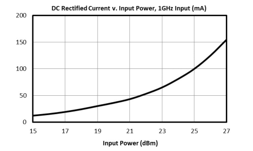
| C | 2019-08-01 | Added DC Current Plot |
NLTL-6273CH
GaAs MMIC Non-Linear Transmission Line
A top-down view of the NLTL-6273’s CH package outline drawing is shown below. The NLTL should only be used in the forward direction, with the input and output ports given in Port Functions.
| Port | Function | Description | DC Equivalent Circuit |
|---|---|---|---|
| GND | Ground | CH package ground path is provided through the substrate and ground bond pads. S package ground provided through metal housing and outer coax conductor. | |
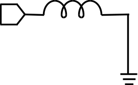
| Pad 1 | Input | Port 1 is diode connected for the CH package and DC short for the S package. | |
| Pad 2 | Output | Port 2 is diode connected for the CH and DC open for the S package. |
NLTL-6273CH
GaAs MMIC Non-Linear Transmission Line
The Absolute Maximum Ratings indicate limits beyond which damage may occur to the device. If these limits are exceeded, the device may be inoperable or have a reduced lifetime.
| Parameter | Maximum Rating | Unit |
|---|---|---|
| Maximum Operating Temperature | 100 | °C |
| Maximum Storage Temperature | 125 | °C |
| Minimum Operating Temperature | -55 | °C |
| Minimum Storage Temperature | -65 | °C |
| Parameter | Details | Rating |
|---|---|---|
| Dimensions | - | 14.22 x 13.21 mm |
The Recommended Operating Conditions indicate the limits, inside which the device should be operated, to guarantee the performance given in Electrical Specifications Operating outside these limits may not necessarily cause damage to the device, but the performance may degrade outside the limits of the electrical specifications. For limits, above which damage may occur, see Absolute Maximum Ratings.
| Parameter | Min | Nominal | Max | Unit |
|---|---|---|---|---|
| Ambient Temperature | -55 | 25 | 100 | °C |
| Input Power | 16 | - | 26 | dBm |
NLTL-6273CH
GaAs MMIC Non-Linear Transmission Line
The electrical specifications apply at Tau=+25°C in a 50Ω system. Typical data shown is for the NLTL used in the forward direction with a +20 dBm sine wave input. Min and Max limits apply only to our connectorized units and are guaranteed at Tau=+25°C. All bare die are 100% DC tested and visually inspected.
| Parameter | Test Conditions | Minimum Frequency (GHz) | Maximum Frequency (GHz) | Min | Typ | Max | Unit |
|---|---|---|---|---|---|---|---|
| Input Frequency Range | - | - | - | 0.7 | - | 5 | GHz |
| Input Power | - | - | - | 16 | - | 26 | dBm |
| Maximum Output Harmonic for given Input | Input = 0.7 GHz | - | - | - | - | 10 | |
| Maximum Output Harmonic for given Input | Input = 1GHz | - | - | - | - | 30 | |
| Maximum Output Harmonic for given Input | Input = 2GHz | - | - | - | - | 17 | |
| Maximum Output Harmonic for given Input | Input = 4GHz | - | - | - | - | 10 | |
| Maximum Output Harmonic for given Input | Input = 5GHz | - | - | - | - | 8 | |
| Output Frequency Range | - | - | - | 0.7 | - | 40 | GHz |
| Parameter | Test Conditions | Minimum Frequency (GHz) | Maximum Frequency (GHz) | Min | Typ | Max | Unit |
|---|---|---|---|---|---|---|---|
| Input Frequency Range | - | - | - | 0.7 | - | 5 | GHz |
| Input Power | - | - | - | 16 | - | 26 | dBm |
| Maximum Output Harmonic for given Input | Input = 0.7 GHz | - | - | - | - | 10 | |
| Maximum Output Harmonic for given Input | Input = 1GHz | - | - | - | - | 30 | |
| Maximum Output Harmonic for given Input | Input = 2GHz | - | - | - | - | 17 | |
| Maximum Output Harmonic for given Input | Input = 4GHz | - | - | - | - | 10 | |
| Maximum Output Harmonic for given Input | Input = 5GHz | - | - | - | - | 8 | |
| Output Frequency Range | - | - | - | 0.7 | - | 40 | GHz |
NLTL-6273CH
GaAs MMIC Non-Linear Transmission Line
NLTL-6273CH
GaAs MMIC Non-Linear Transmission Line
NLTL-6273CH
GaAs MMIC Non-Linear Transmission Line
NLTL-6273CH
GaAs MMIC Non-Linear Transmission Line
NLTL-6273CH
GaAs MMIC Non-Linear Transmission Line
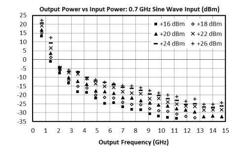
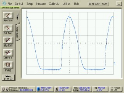
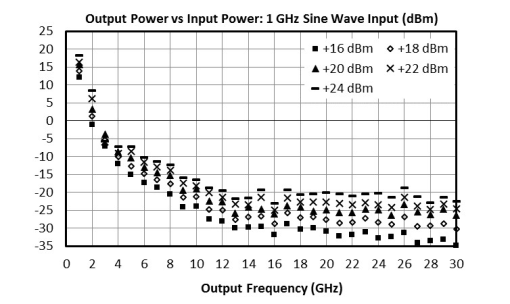
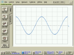
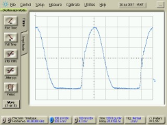
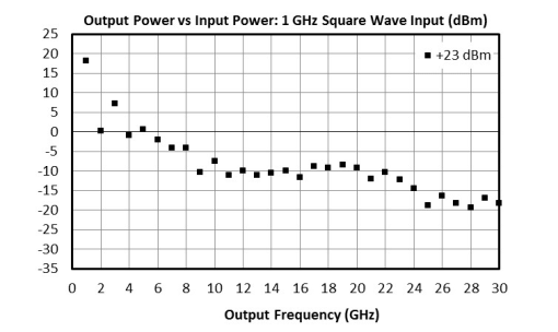
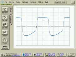
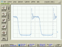
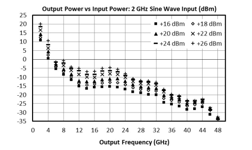
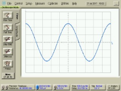
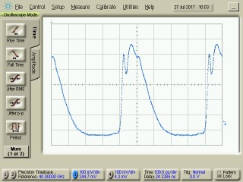
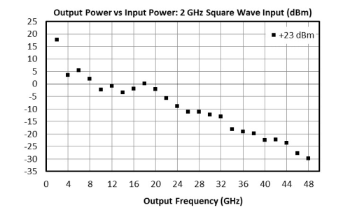
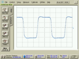
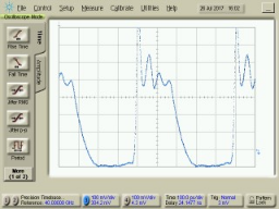
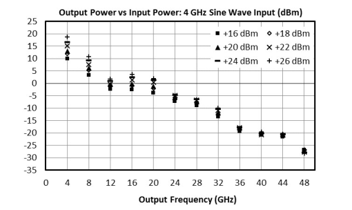
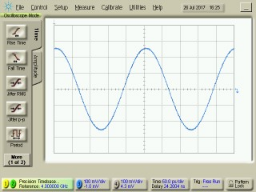
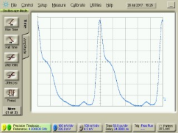
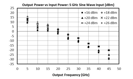
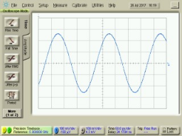
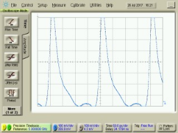
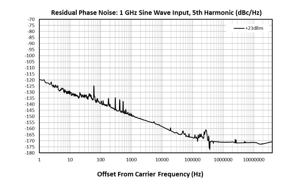
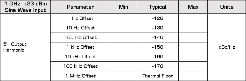
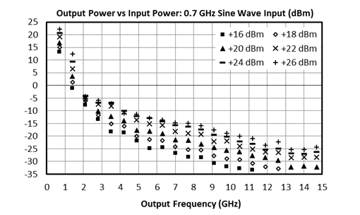
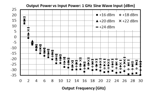
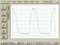
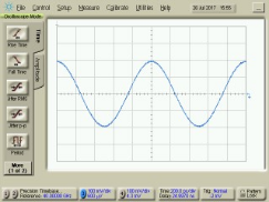
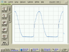
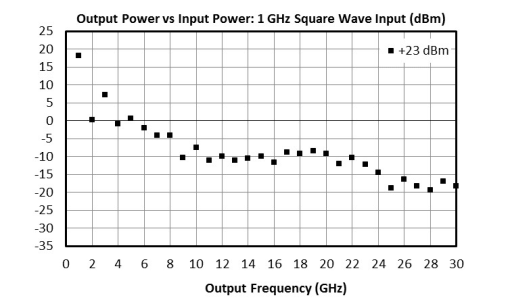
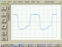
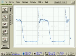
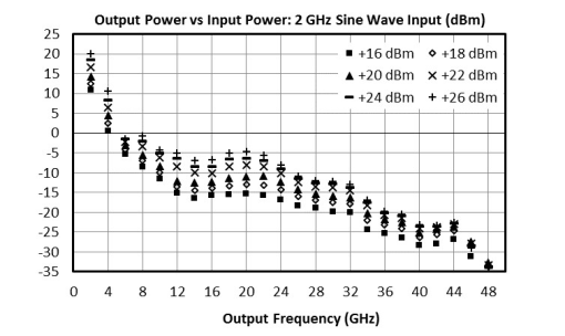
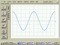
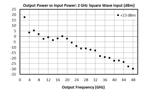
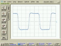
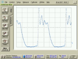
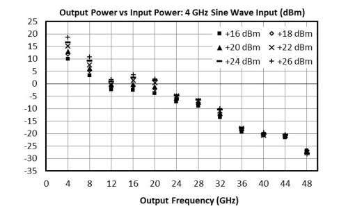
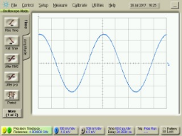
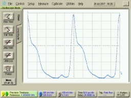
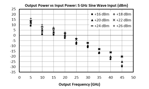
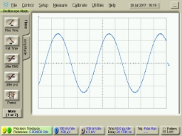
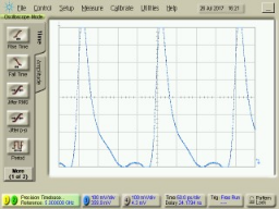
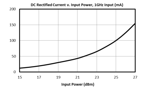
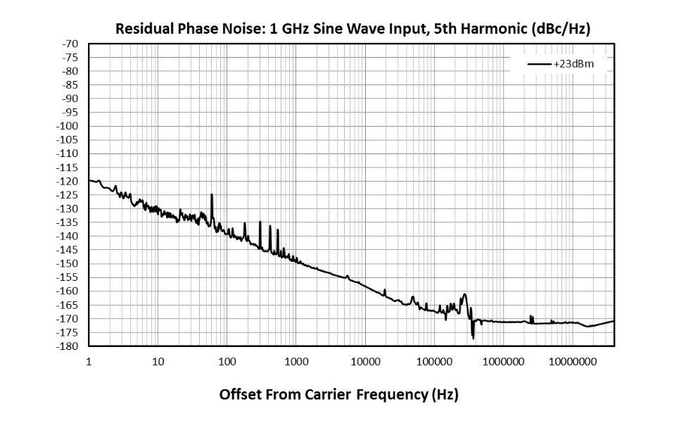
Performance plots for the connectorized module are shown for measurements where directly probed measurements of the die are unavailable. Note that the following measurements include losses from connectors and microstrip traces.
NLTL-6273CH
GaAs MMIC Non-Linear Transmission Line
NLTL-6273CH
GaAs MMIC Non-Linear Transmission Line
NLTL-6273CH
GaAs MMIC Non-Linear Transmission Line