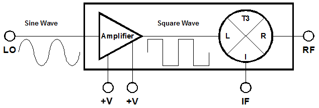
Port Diagram
Sales: 408-778-9952 | General: 408-778-4200 | Fax: 408-778-4300
Sales & Customer Support: [email protected]
Tech Support: [email protected]
The MT3A-0113H is a versatile, robust, and broadband Two-Tone-Terminator mixer integrated with a low phase noise LO driver amplifier. The MT3A-0113H employs the most sophisticated mixer on the market today and offers unparalleled performance when compared to all other mixer technologies. The MT3A-0113H delivers exceptional IMD suppression with low conversion loss and high IP3. The integrated positive bias only LO amplifier allows for high linearity with LO drive levels down to just +5dBm.

N/A
| Part Number | Description | Package | Connectors | Green Status | Product Lifecycle | Export Classification |
|---|---|---|---|---|---|---|
| MT3A-0113HPA | Two-Tone-Terminator Mixer/LO-Amplifier | PA | Standard | REACH RoHS REACH RoHS | Released | EAR99 |
| MT3A-0113HCH-2 | Two-Tone-Terminator Mixer/LO-Amplifier | CH | - | REACH RoHS REACH RoHS | Released | EAR99 |
MT3A-0113HCH-2
Two-Tone-Terminator Mixer/LO-Amplifier
| Revision Code | Revision Date | Comment |
|---|---|---|
| - | 2020-11-10 | Datasheet Initial Release |
| A | 2020-11-17 | |
| B | 2021-04-23 | LO to RF/IF Leakage Plots Updated |
| C | 2021-06-09 | RF/LO Absolute Maximum Power Handling Updated |
MT3A-0113HCH-2
Two-Tone-Terminator Mixer/LO-Amplifier
MT3A-0113HCH-2
Two-Tone-Terminator Mixer/LO-Amplifier
| Port | Function | Description | DC Equivalent Circuit |
|---|---|---|---|
| GND | Ground | CH package ground path is provided through the substrate and ground bond pads. |  |
| Port 1 | LO | The LO port is DC blocked and AC matched to 50 Ohms from 1 GHz to 13 GHz. |  |
| Port 2 | IF | The IF port is DC blocked and AC matched to 50 Ohms from 500 MHz to 8.5 GHz. |  |
| Port 3 | RF | The RF port is DC short to ground and AC matched to 50 Ohms from 1 GHz to 13 GHz. Blocking capacitor is optional. | - |
| Port 4 | VC | Port VC is the DC voltage supply for that supplies the amplifier’s collector current. It is connected internally through the amplifier die’s RF output port. |  |
| Port 5 | VB | Port VB is the DC voltage bias for the current mirror that controls collector current supplied to the amplifier. Larger voltages result in a higher current draw through port VC, effectively functioning as a gain control pin of the amplifier |  |
MT3A-0113HCH-2
Two-Tone-Terminator Mixer/LO-Amplifier
The Absolute Maximum Ratings indicate limits beyond which damage may occur to the device. If these limits are exceeded, the device may become inoperable or have a reduced lifetime
| Parameter | Maximum Rating | Unit |
|---|---|---|
| DC Bias Current | 150 | mA |
| DC Voltage on VB or VC | 8 | V |
| LO Power Handling | 16 | dBm |
| Maximum Operating Temperature | 85 | °C |
| Maximum Storage Temperature | 125 | °C |
| Minimum Operating Temperature | -55 | °C |
| Minimum Storage Temperature | 65 | °C |
| RF Power Handling | 16 | dBm |
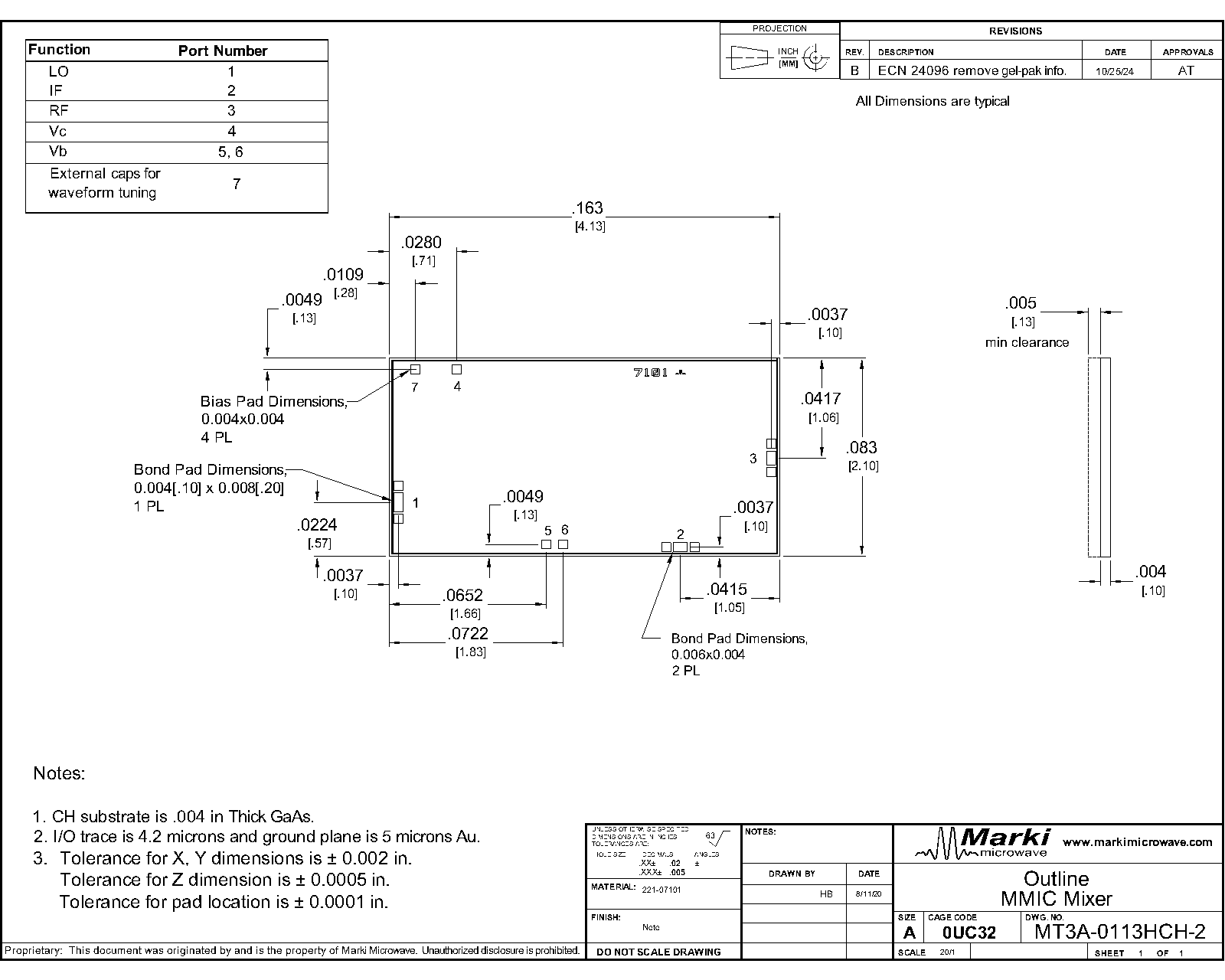
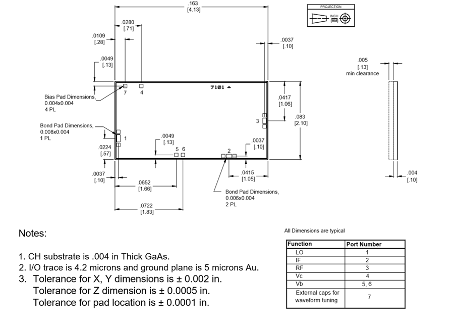
| Parameter | Details | Rating |
|---|---|---|
| Dimensions | - | 4.13 x 2.10 mm |
The Recommended Operating Conditions indicate the limits, inside which the device should be operated, to guarantee the performance given in Electrical Specifications Operating outside these limits may not necessarily cause damage to the device, but the performance may degrade outside the limits of the electrical specifications. For limits, above which damage may occur, see Absolute Maximum Ratings.
| Parameter | Min | Nominal | Max | Unit |
|---|---|---|---|---|
| Ambient Temperature | -40 | 25 | 85 | °C |
| Positive DC Voltage | 5 | 7 | 1 | V |
| Quiescent DC Current (Ic) | 26 | 44 | 65 | mA |
| DC Current with RF Input (Ic) | - | - | 150 | mA |
| Positive DC Current Mirror Voltage (VB) | 5 | 6 | 8 | V |
| Input Power for Saturation | - | 10 | 16 | dBm |
| LO Input Power | 3 | - | 15 | - |
MT3A-0113HCH-2
Two-Tone-Terminator Mixer/LO-Amplifier
Specifications guaranteed from -55°C to +100°C, measured in a 50Ω system.
| Parameter | Test Conditions | Min | Typ | Max | Unit |
|---|---|---|---|---|---|
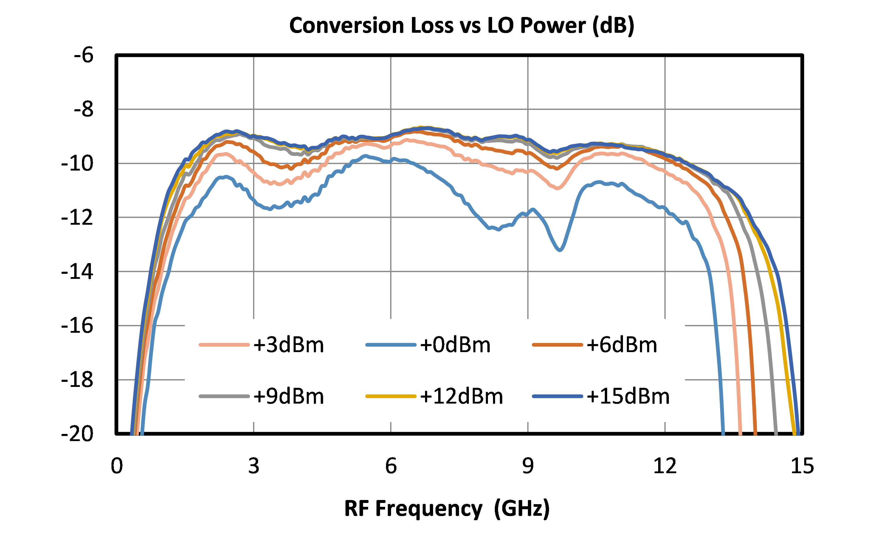
| Conversion Loss | LO/RF=1-13 GHz IF= 0.5-2.0 GHz | - | 9.5 | 14 | dB |
| Conversion Loss | LO/RF=1-13 GHz IF= 2.0-8.5 GHz | - | 11.5 | - | dB |
| Current Consumption | +6.0VB/+7.0VC | 80 | 120 | 150 | mA |
| IF Frequency Range | - | 0.5 | - | 8.5 | GHz |
| Input P0.1 dB | LO/RF=1-13 GHz | - | 13 | - | dBm |
| LO Drive Level | - | 5 | 8 | 15 | dBm |
| LO Frequency Range | - | 1 | - | 13 | GHz |
| RF Frequency Range | - | 1 | - | 13 | GHz |
| Input IP3 | - | - | 28 | - | dBm |
| Parameter | Test Conditions | Min | Typ | Max | Unit |
|---|---|---|---|---|---|
| Conversion Loss | LO/RF=1-13 GHz IF= 0.5-2.0 GHz | - | 9.5 | 14 | dB |
| Conversion Loss | LO/RF=1-13 GHz IF= 2.0-8.5 GHz | - | 11.5 | - | dB |
| Current Consumption | +6.0VB/+7.0VC | 80 | 120 | 150 | mA |
| IF Frequency Range | - | 0.5 | - | 8.5 | GHz |
| Input P0.1 dB | LO/RF=1-13 GHz | - | 13 | - | dBm |
| LO Drive Level | - | 5 | 8 | 15 | dBm |
| LO Frequency Range | - | 1 | - | 13 | GHz |
| RF Frequency Range | - | 1 | - | 13 | GHz |
| Input IP3 | - | - | 28 | - | dBm |
MT3A-0113HCH-2
Two-Tone-Terminator Mixer/LO-Amplifier


MT3A-0113HCH-2
Two-Tone-Terminator Mixer/LO-Amplifier


MT3A-0113HCH-2
Two-Tone-Terminator Mixer/LO-Amplifier
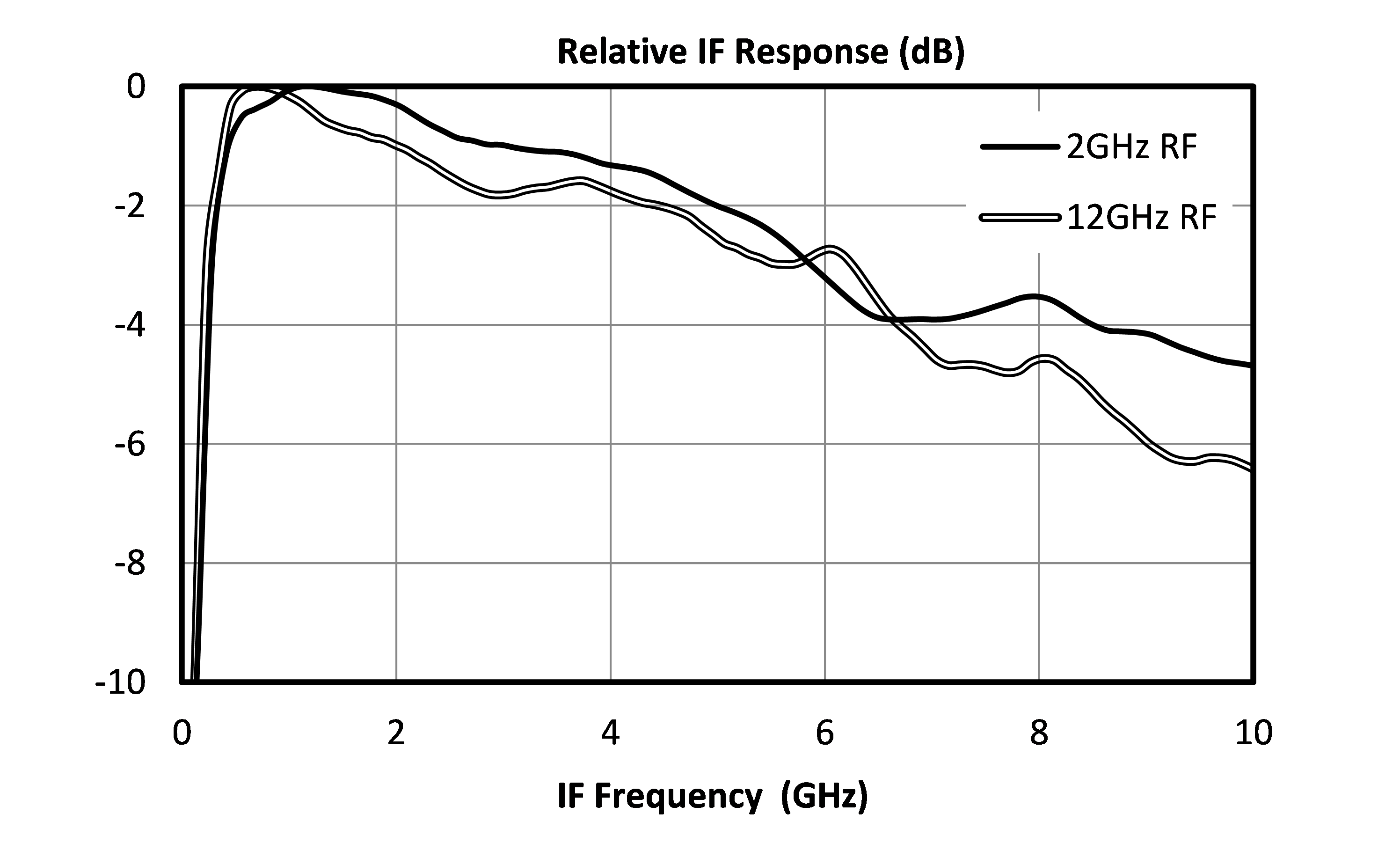
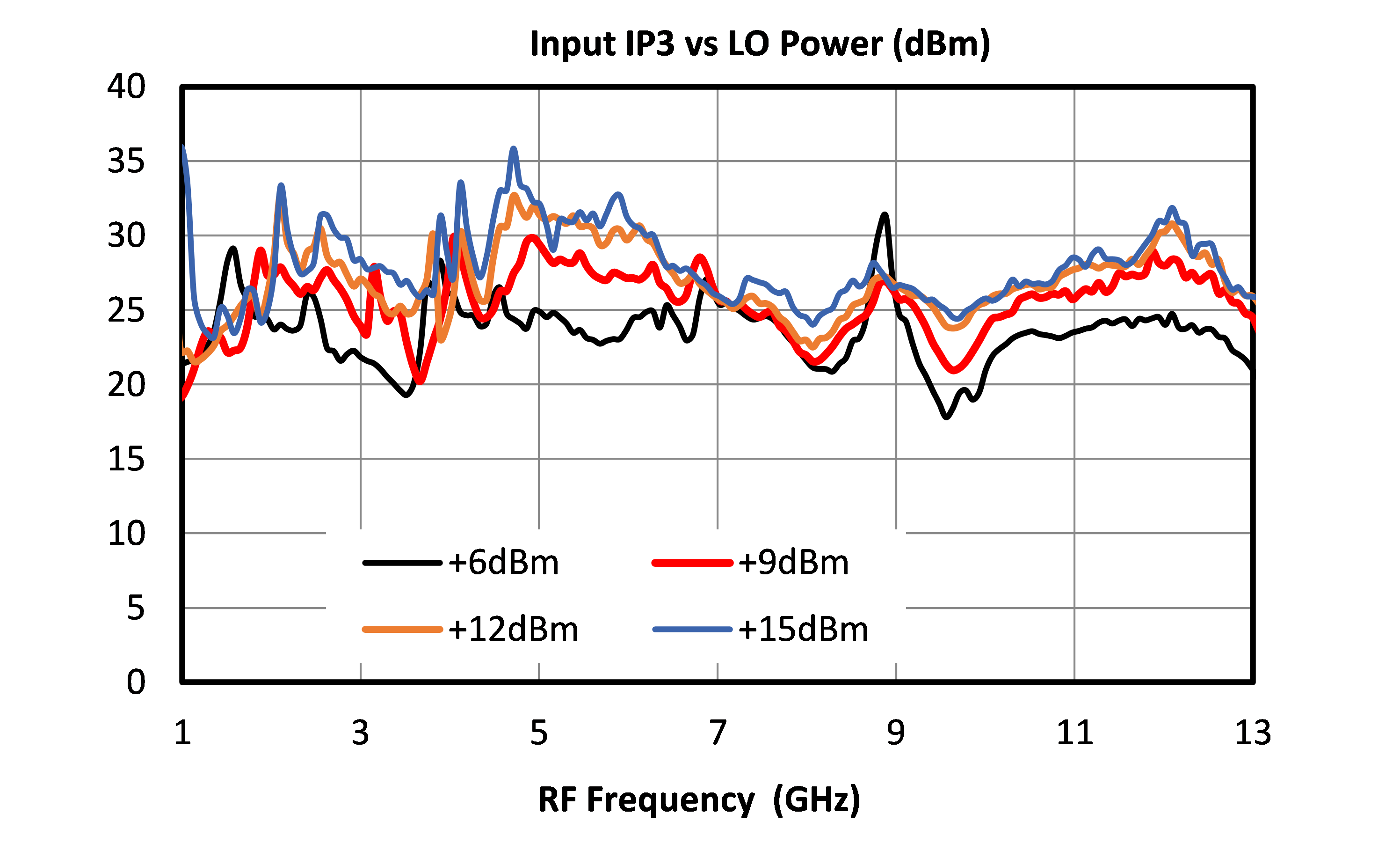
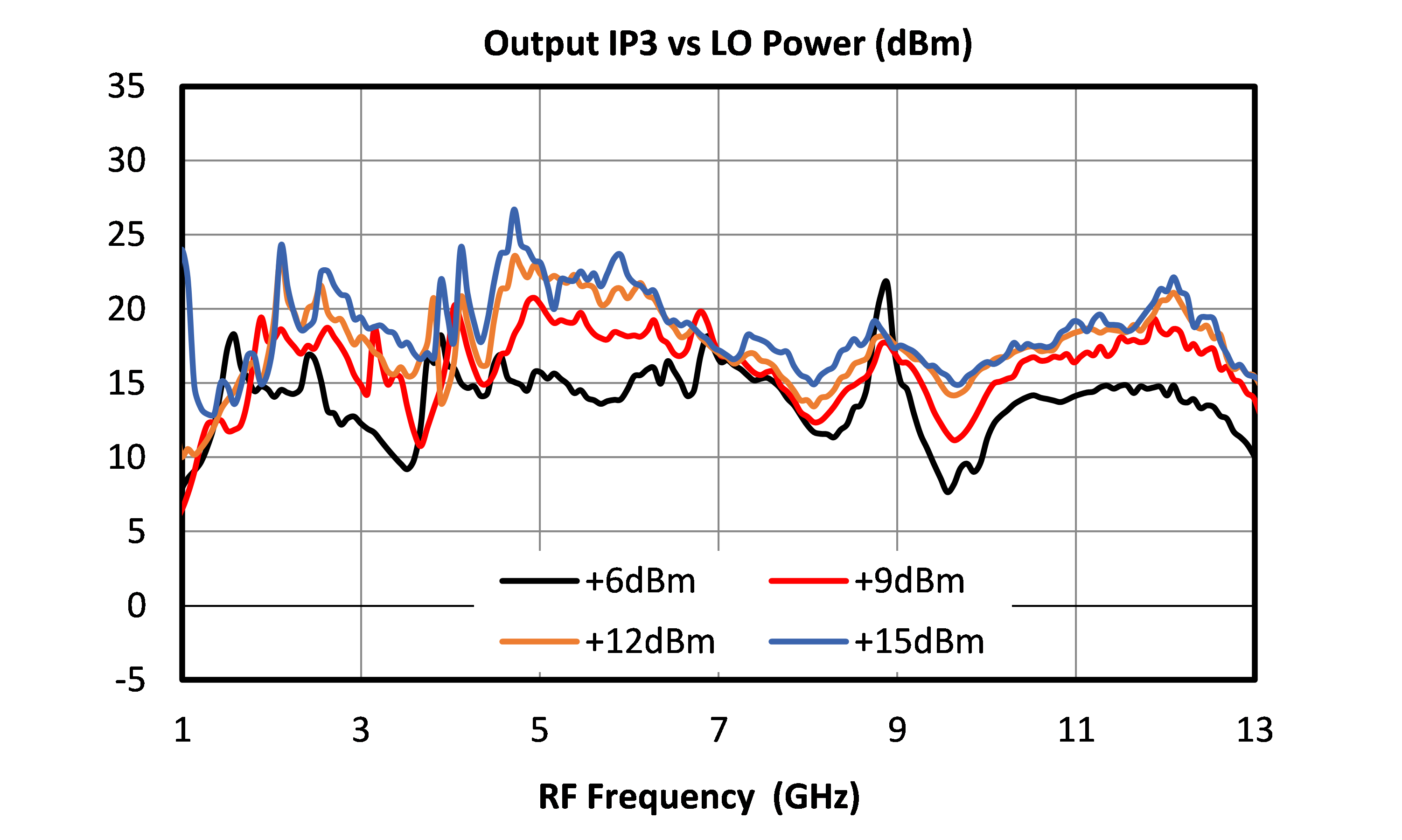
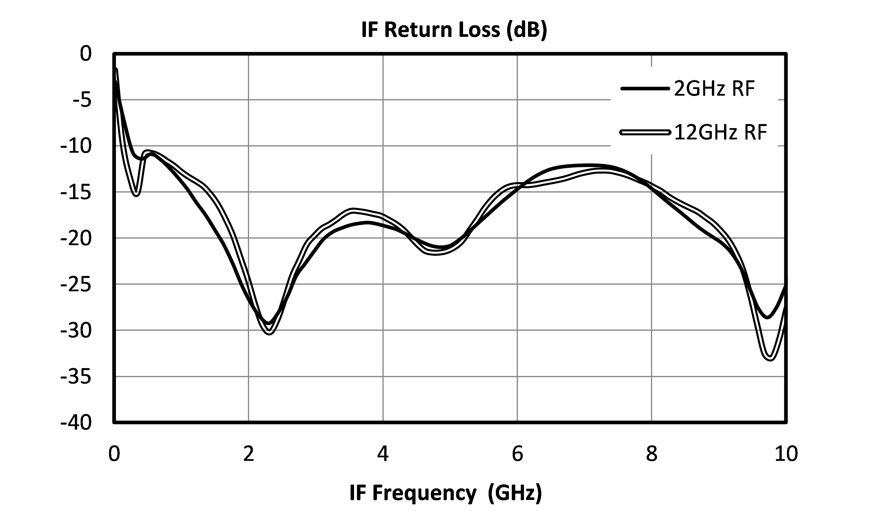
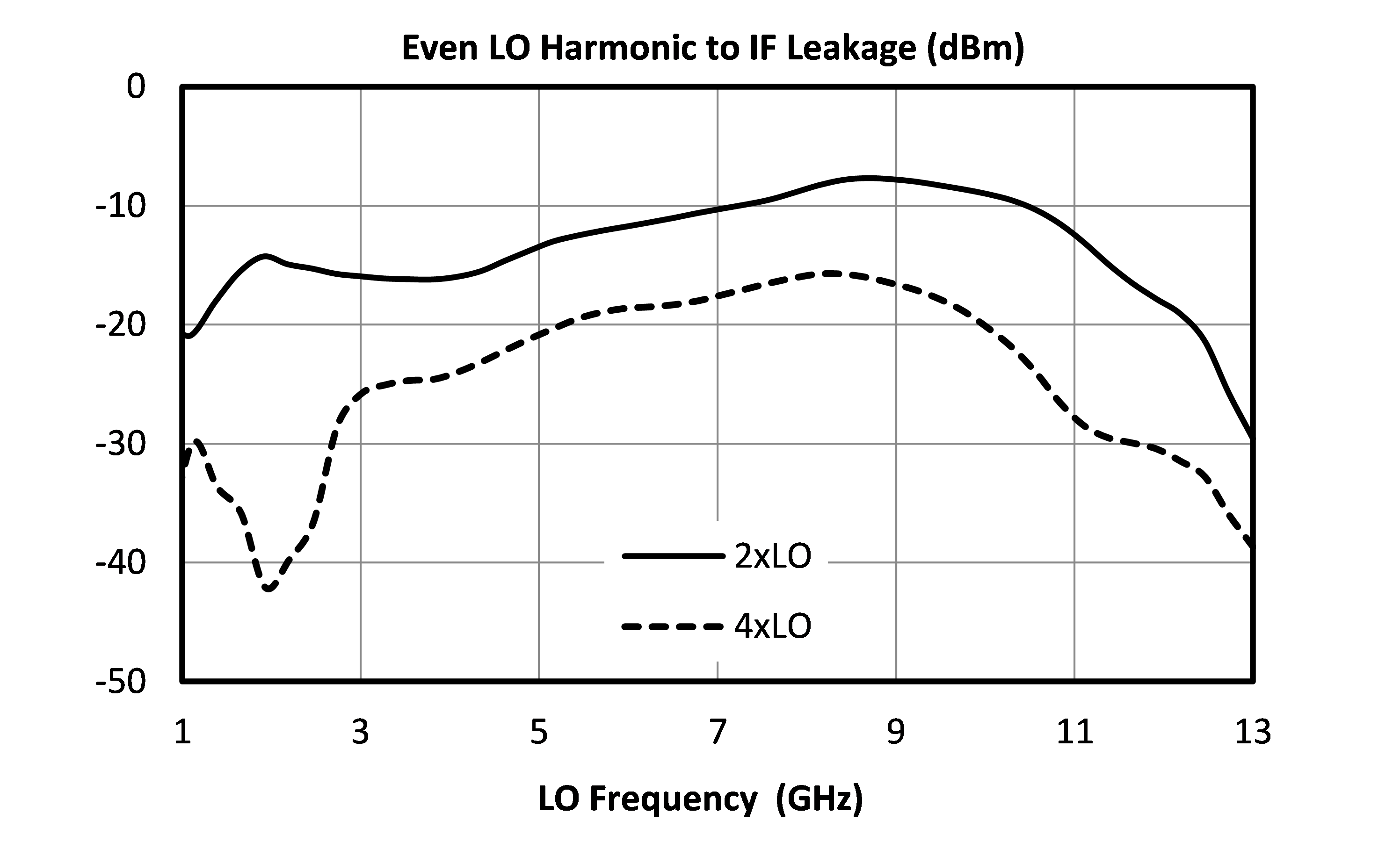
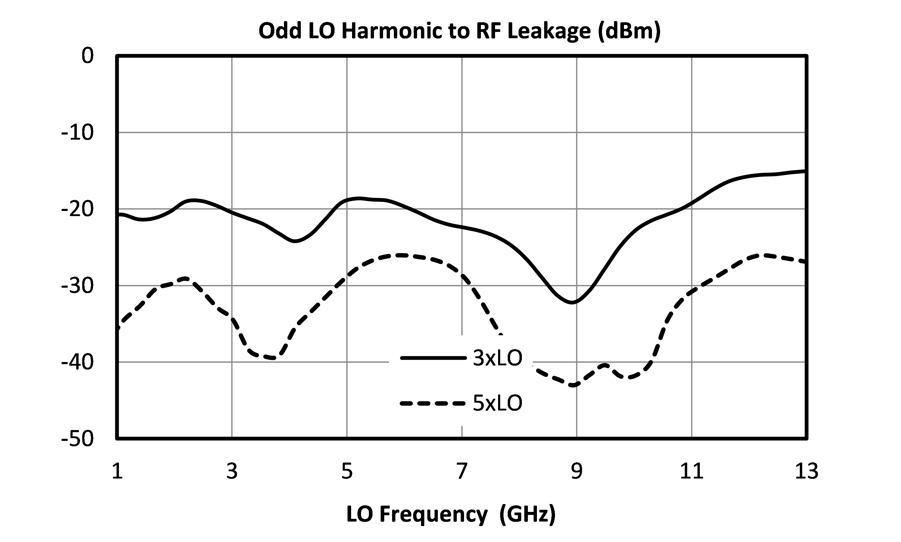
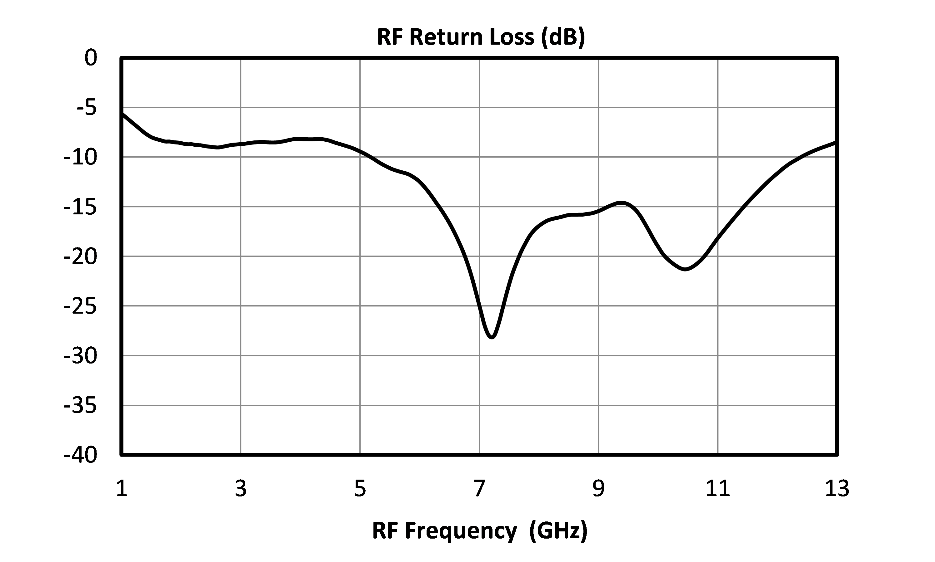
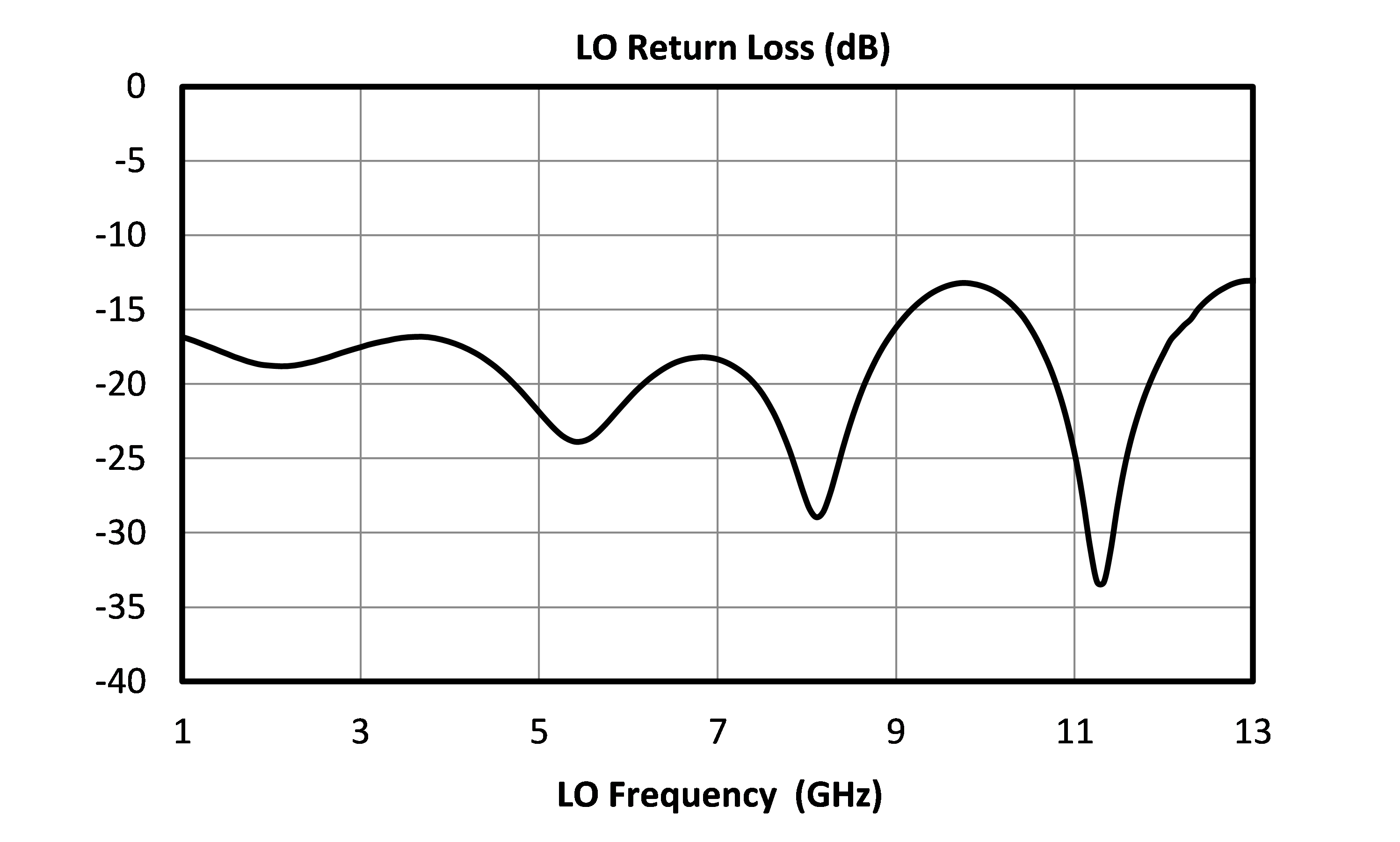
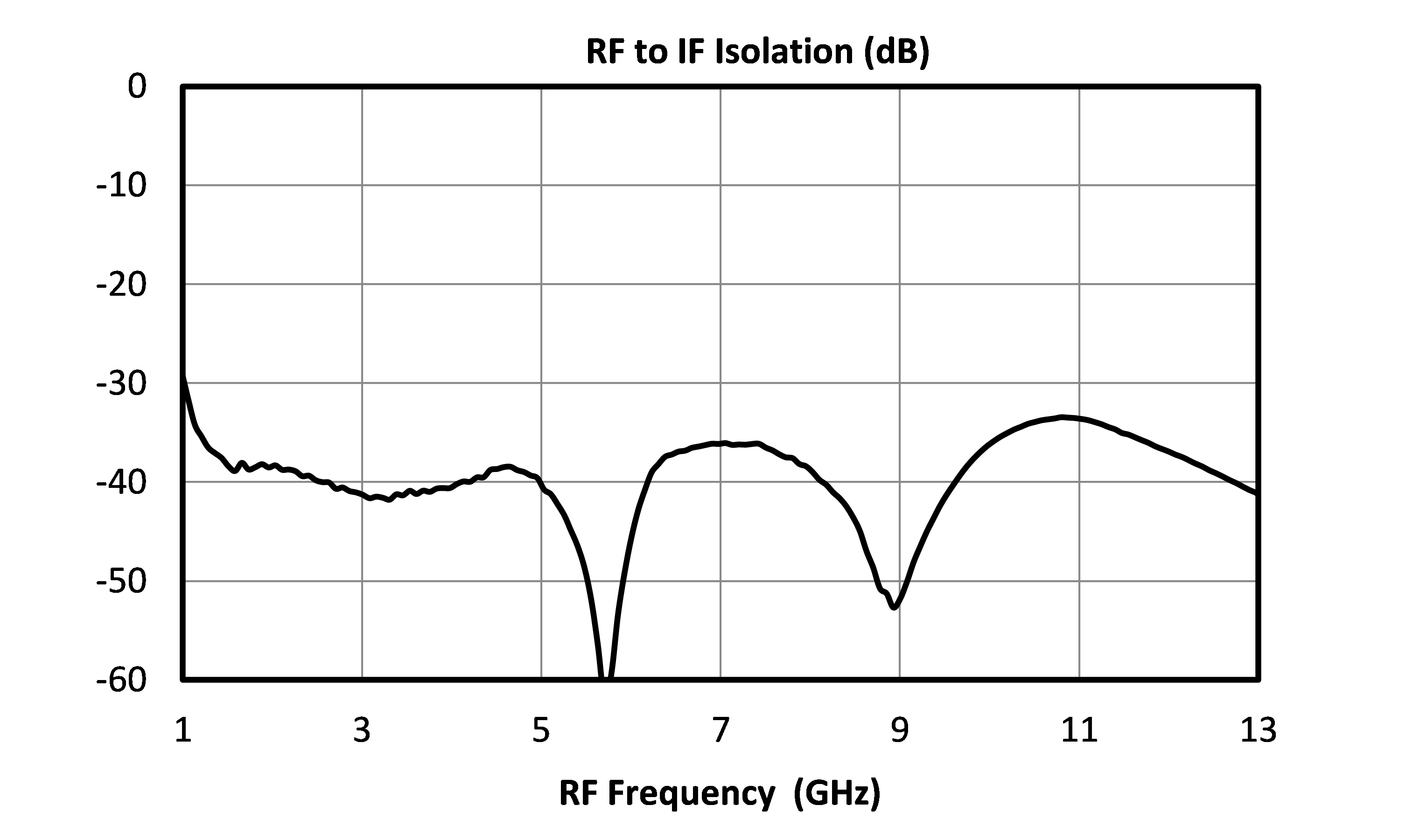
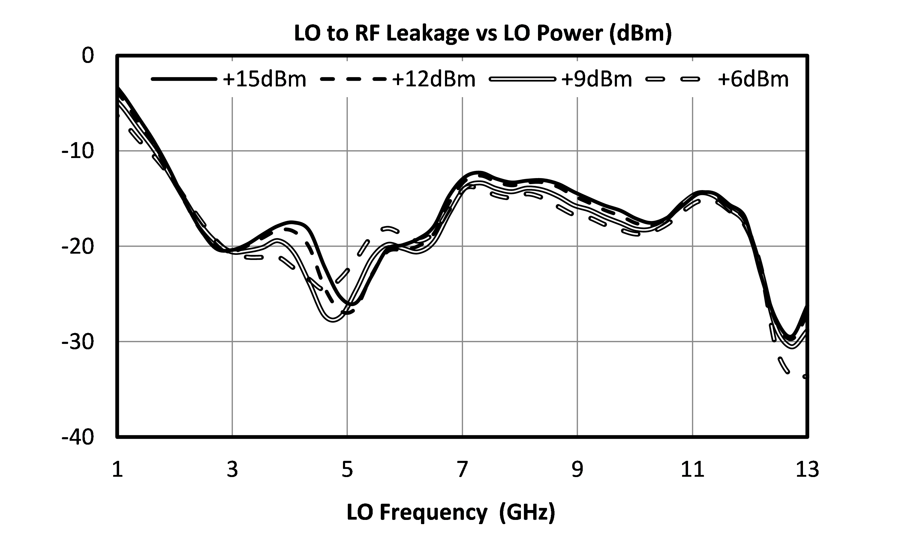
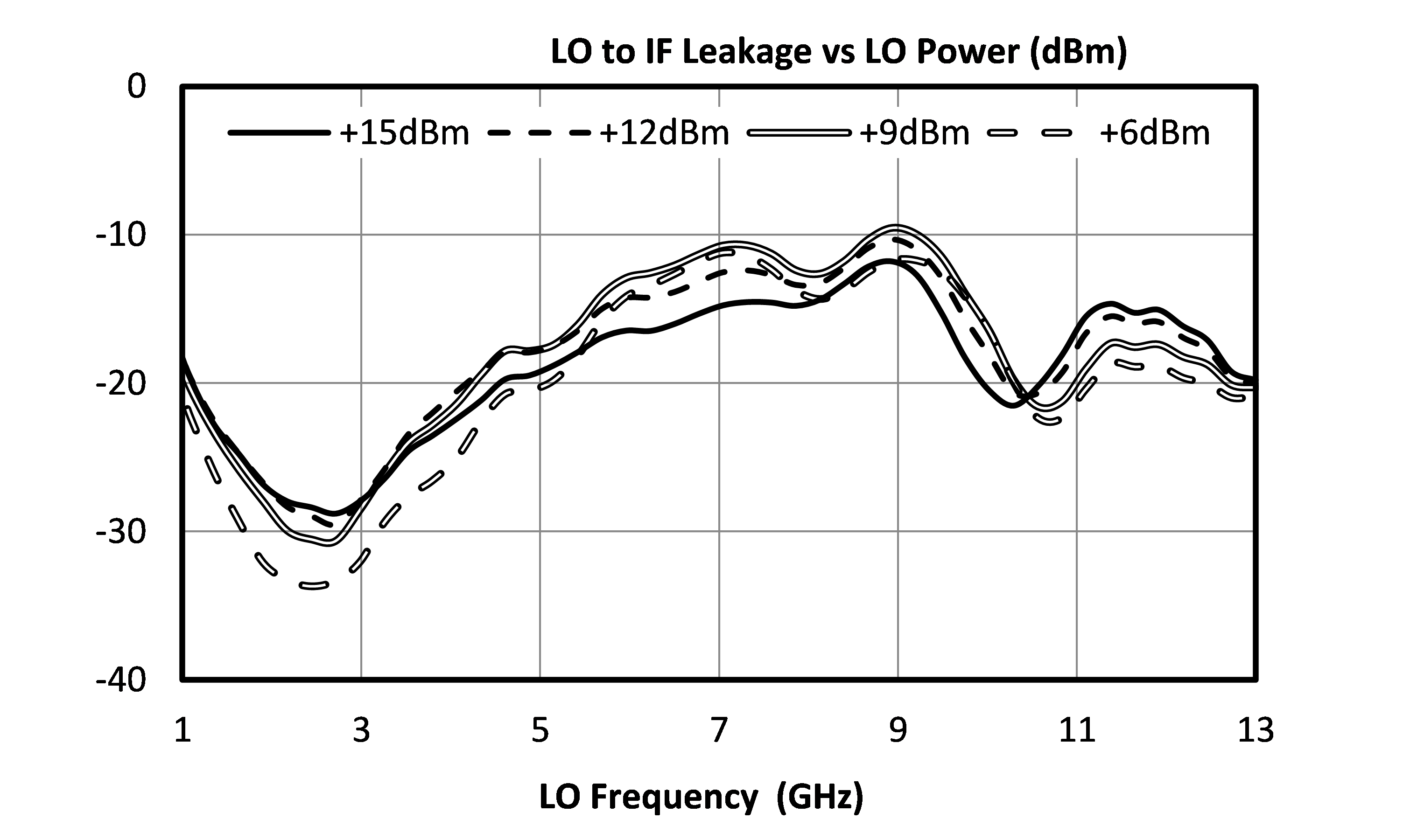
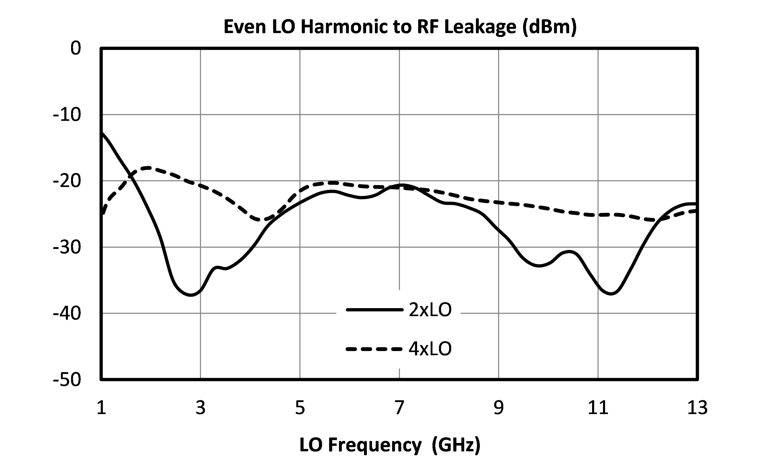
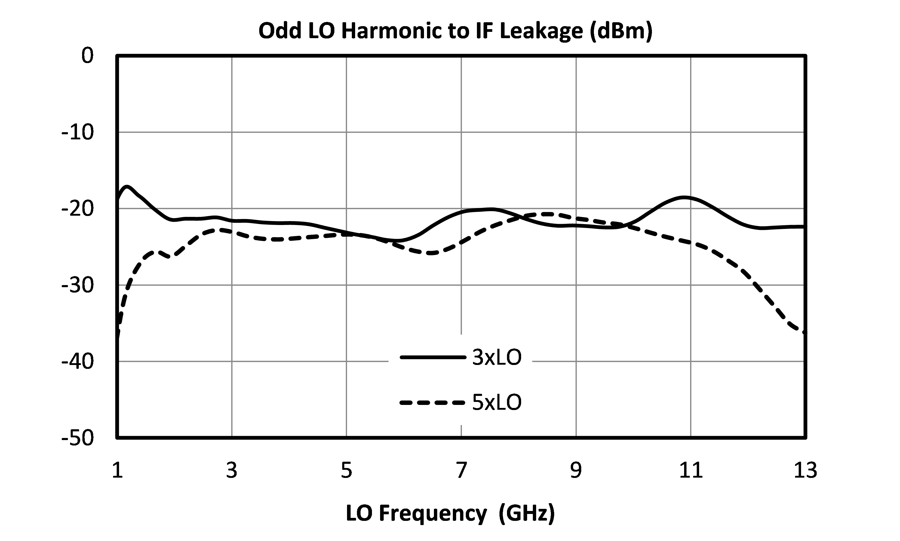
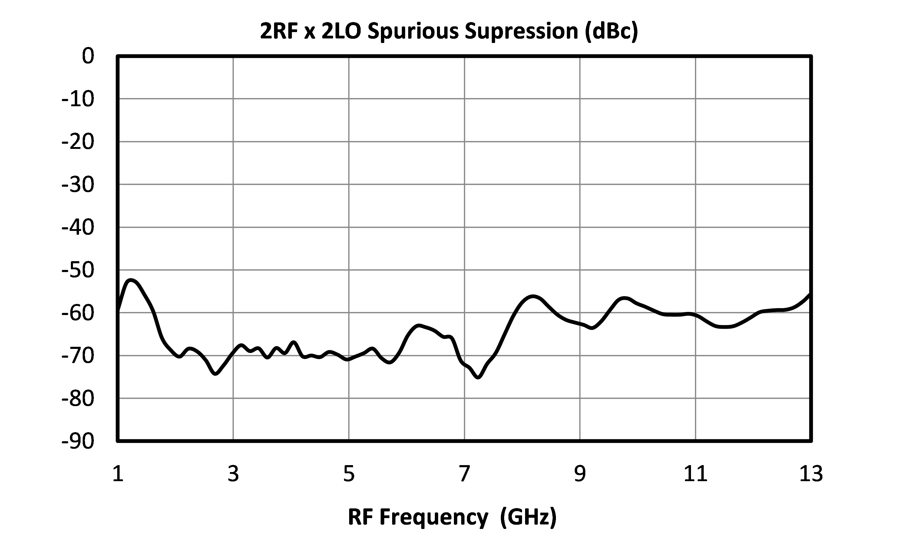
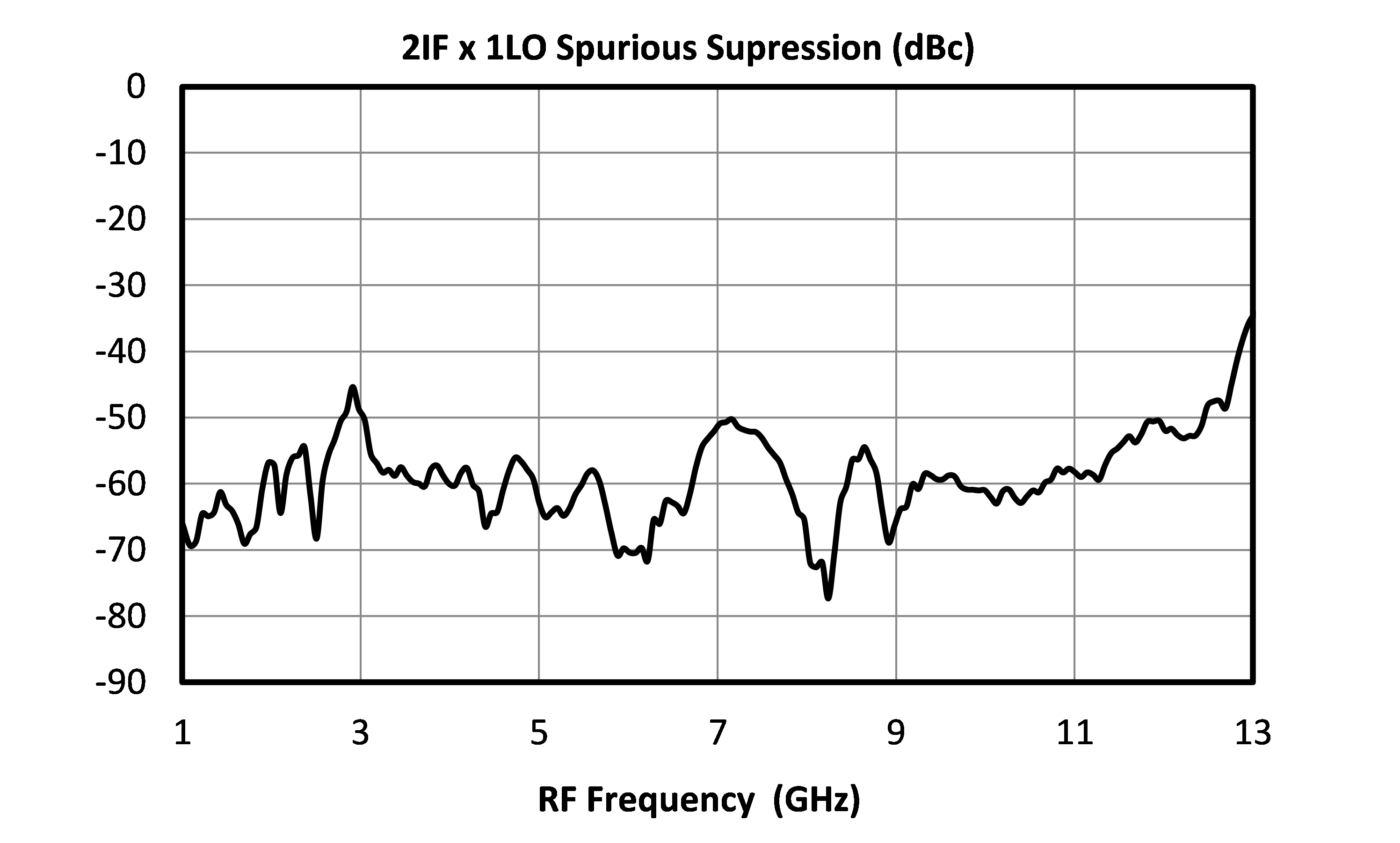
Performance plots for the connectorized module are shown for measurements where directly probed measurements of the die are unavailable. Note that the following measurements include losses from connectors and microstrip traces.


MT3A-0113HCH-2
Two-Tone-Terminator Mixer/LO-Amplifier


MT3A-0113HCH-2
Two-Tone-Terminator Mixer/LO-Amplifier