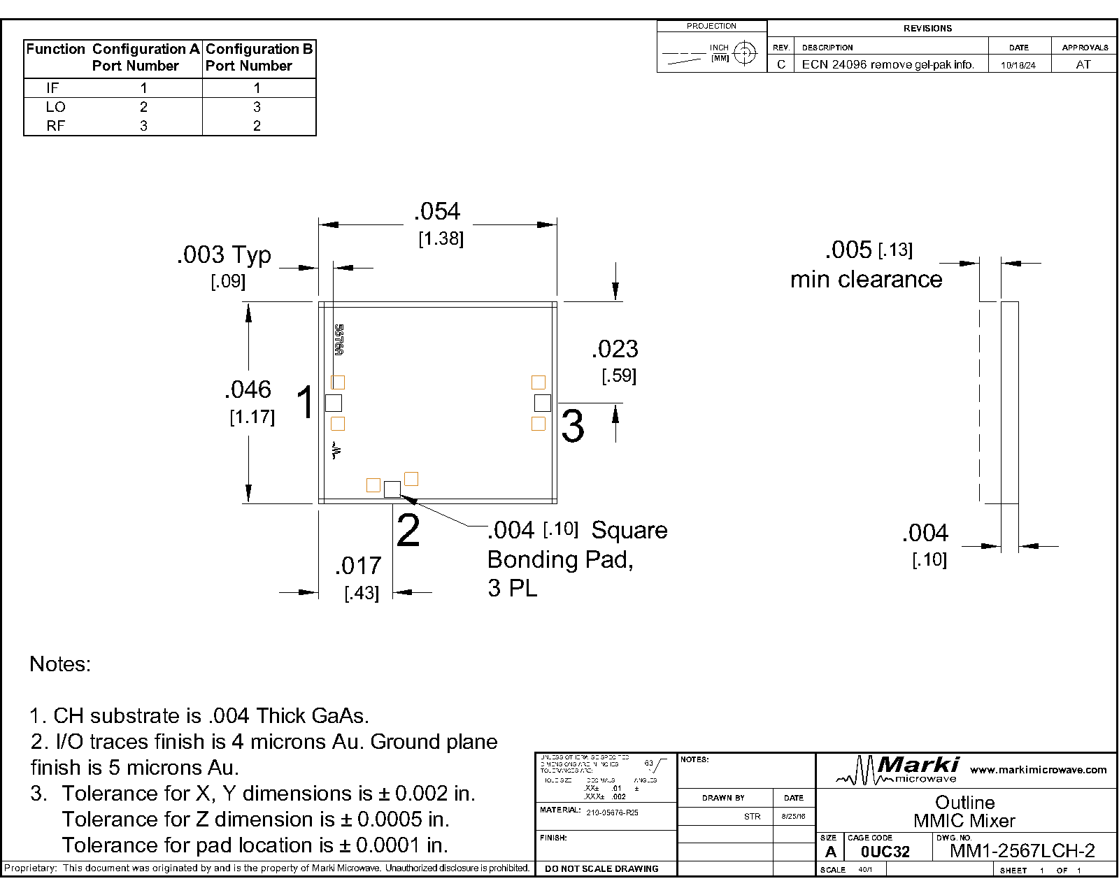
Port Diagram


Sales: 408-778-9952 | General: 408-778-4200 | Fax: 408-778-4300
Sales & Customer Support: [email protected]
Tech Support: [email protected]
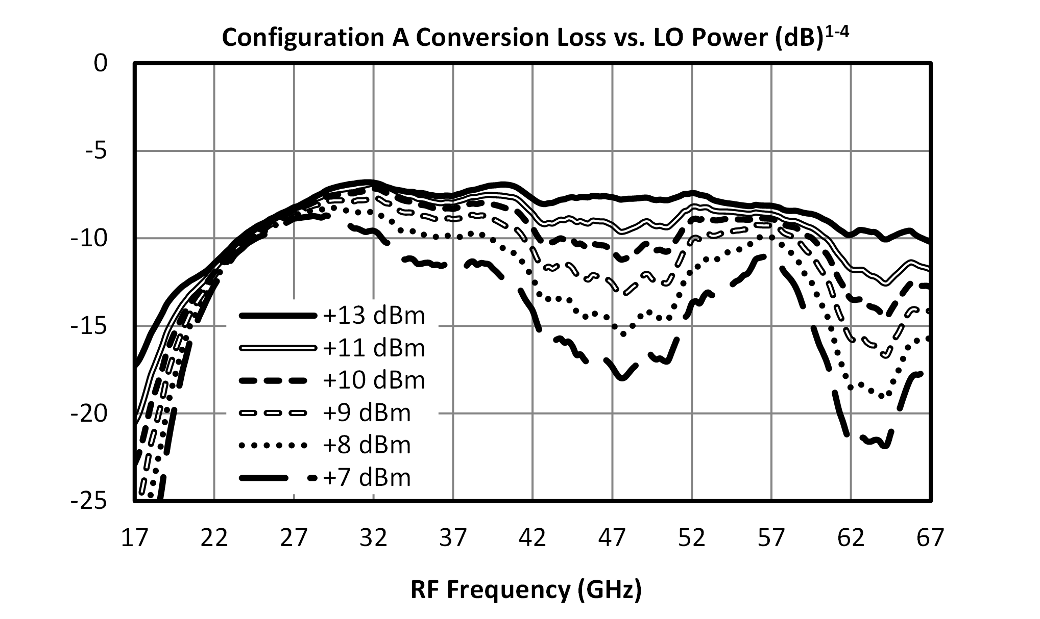
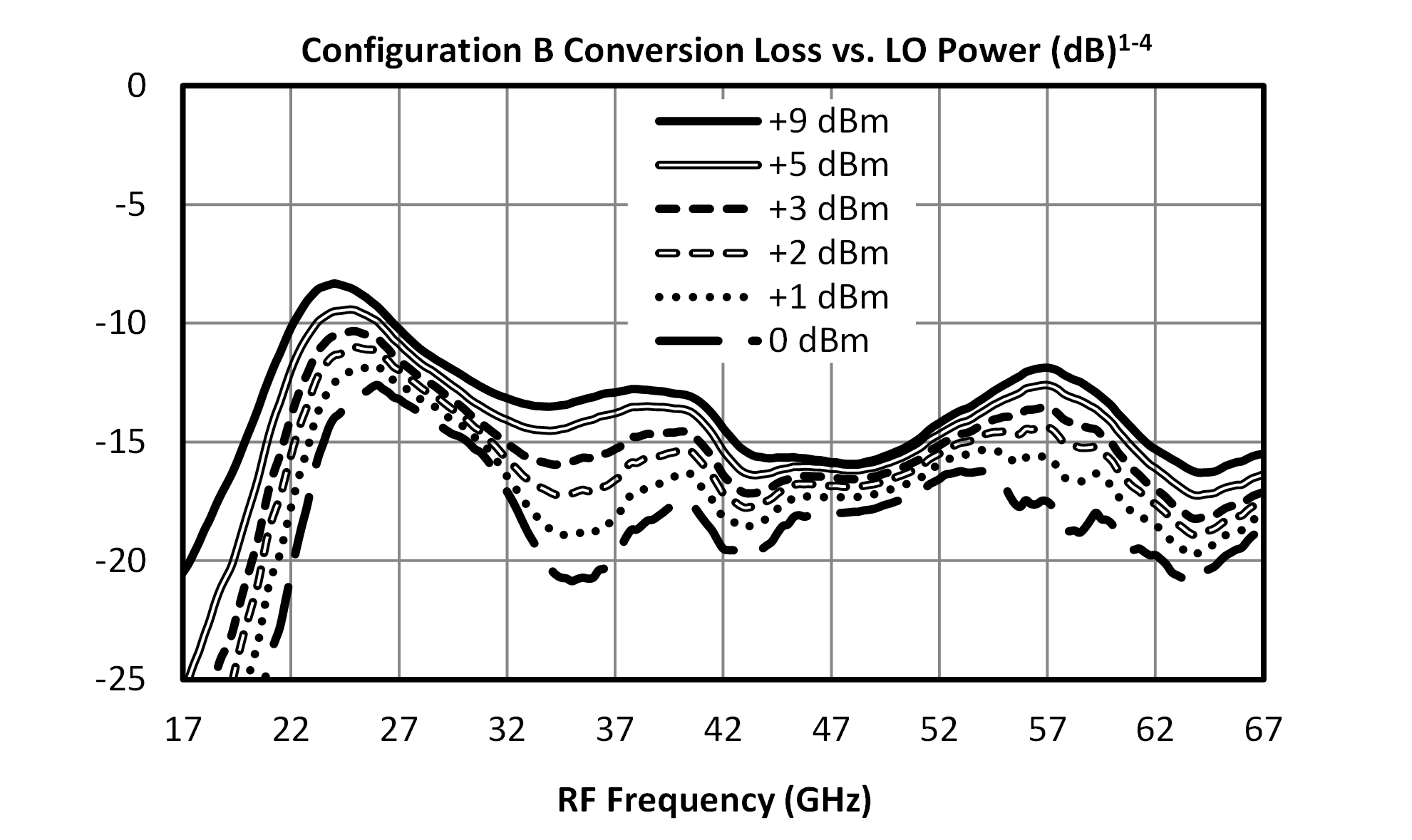
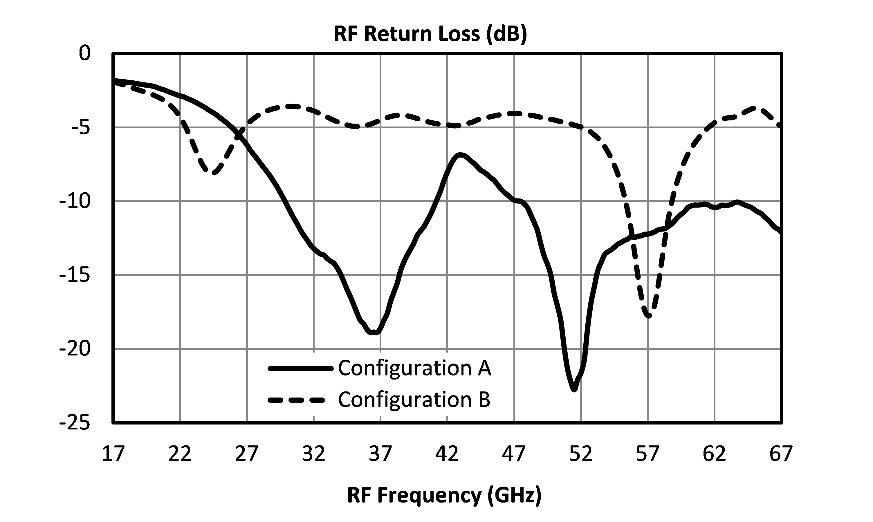
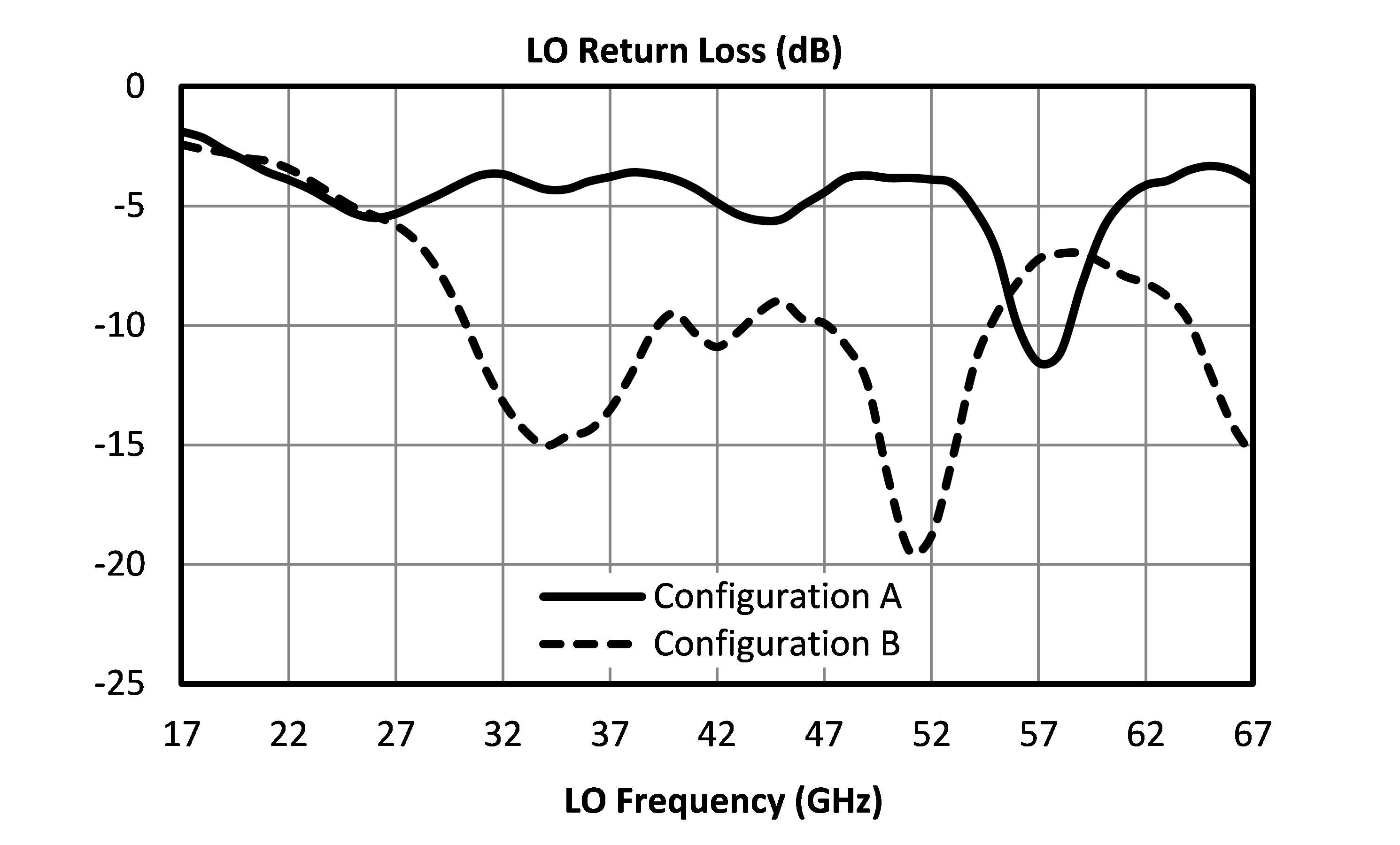
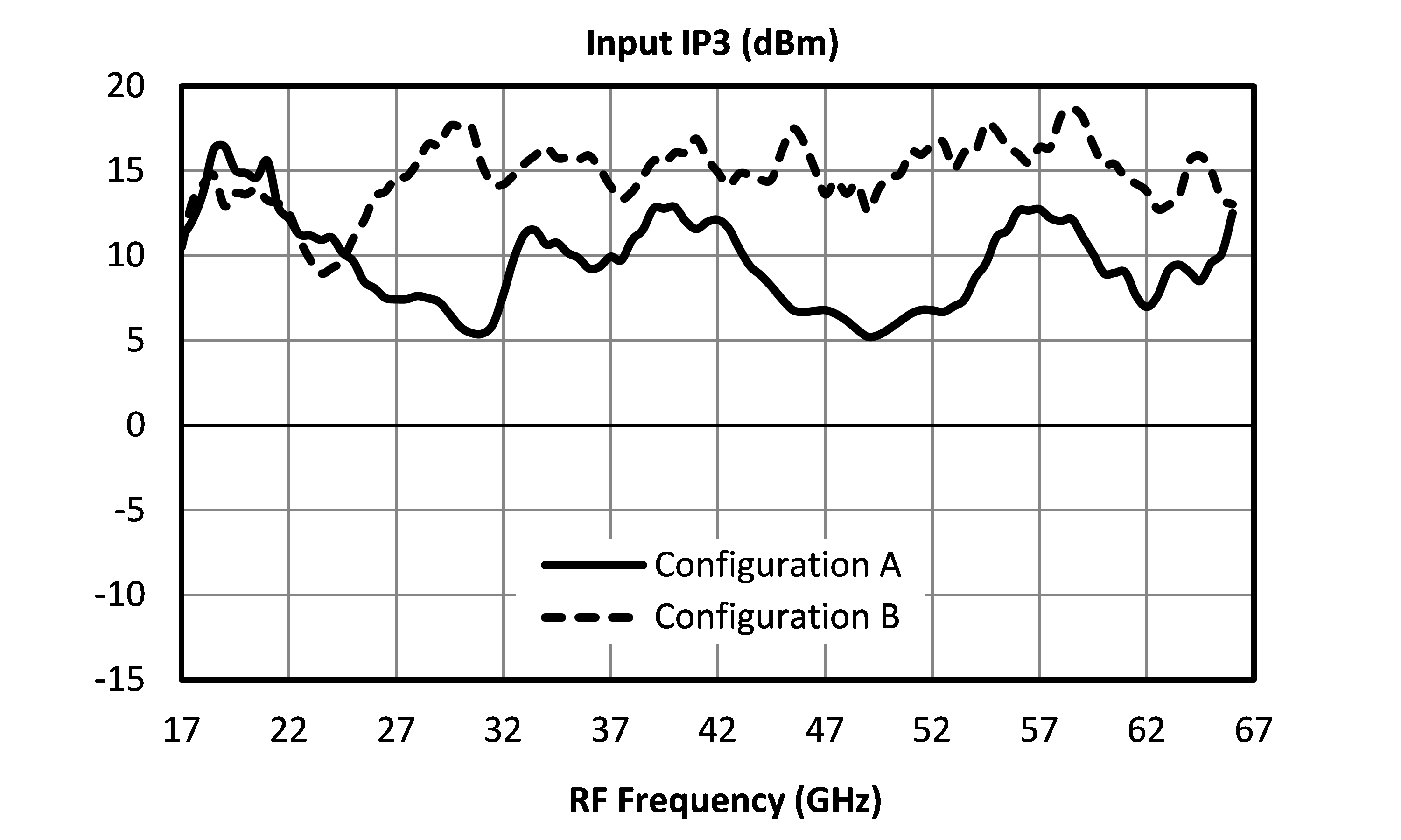
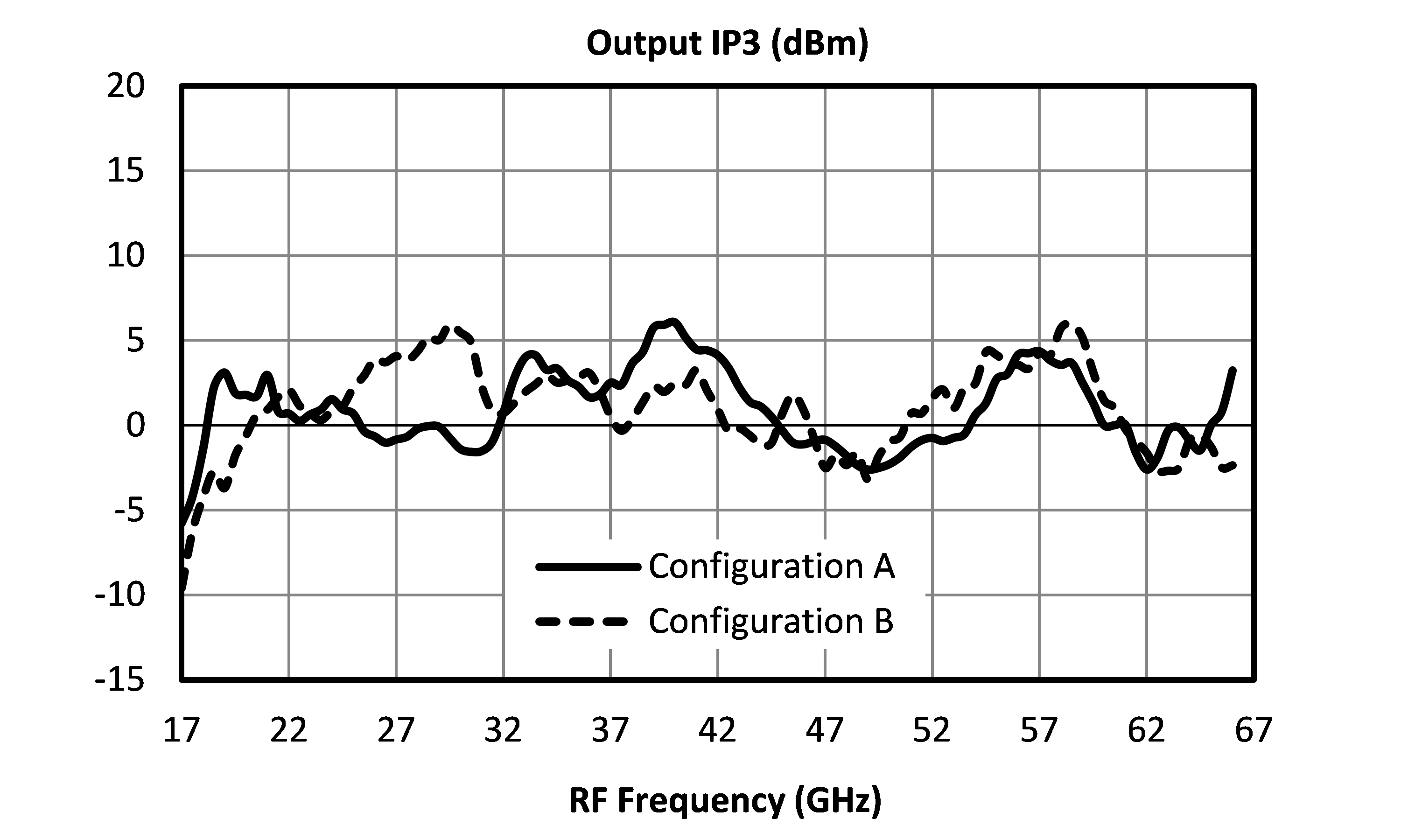
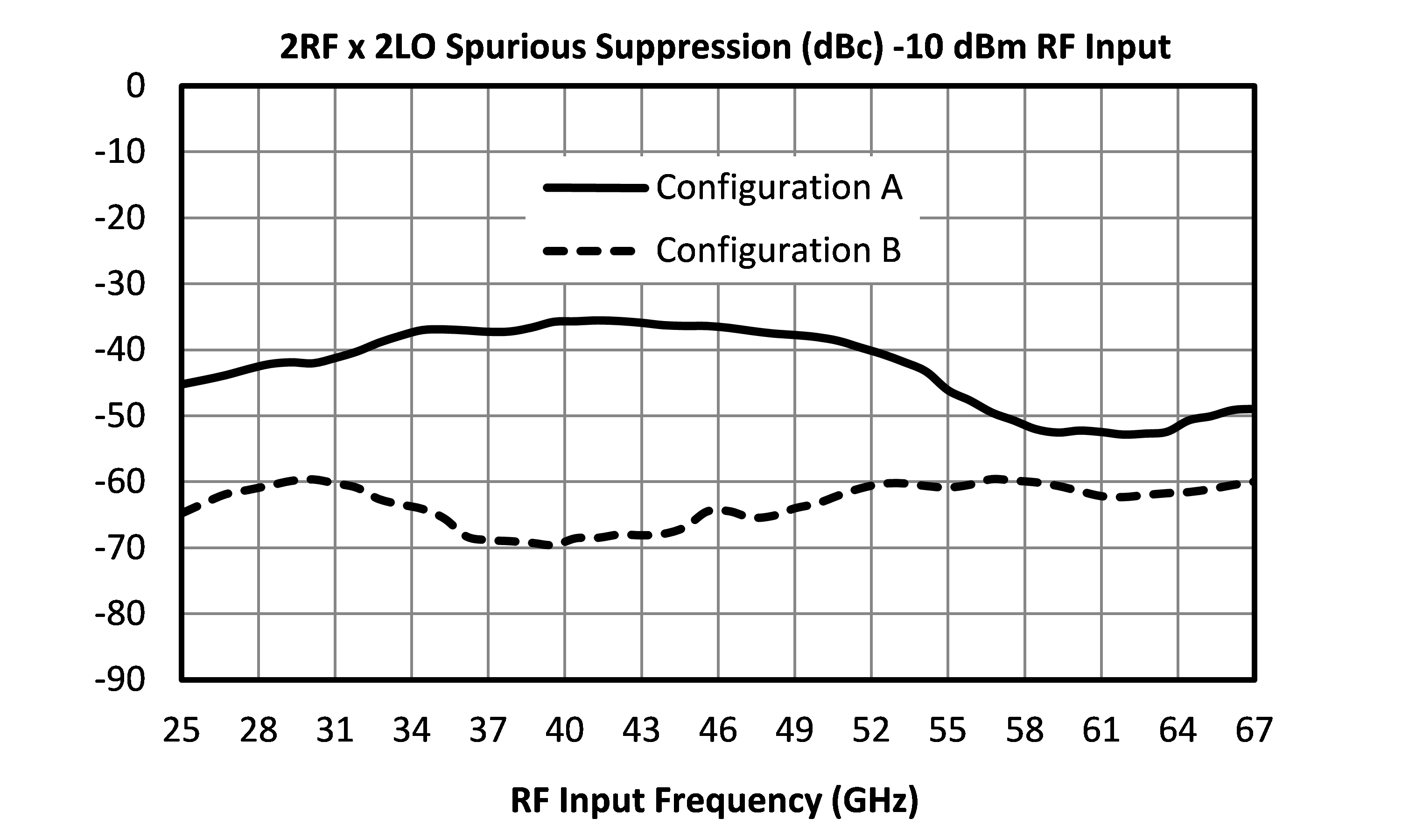
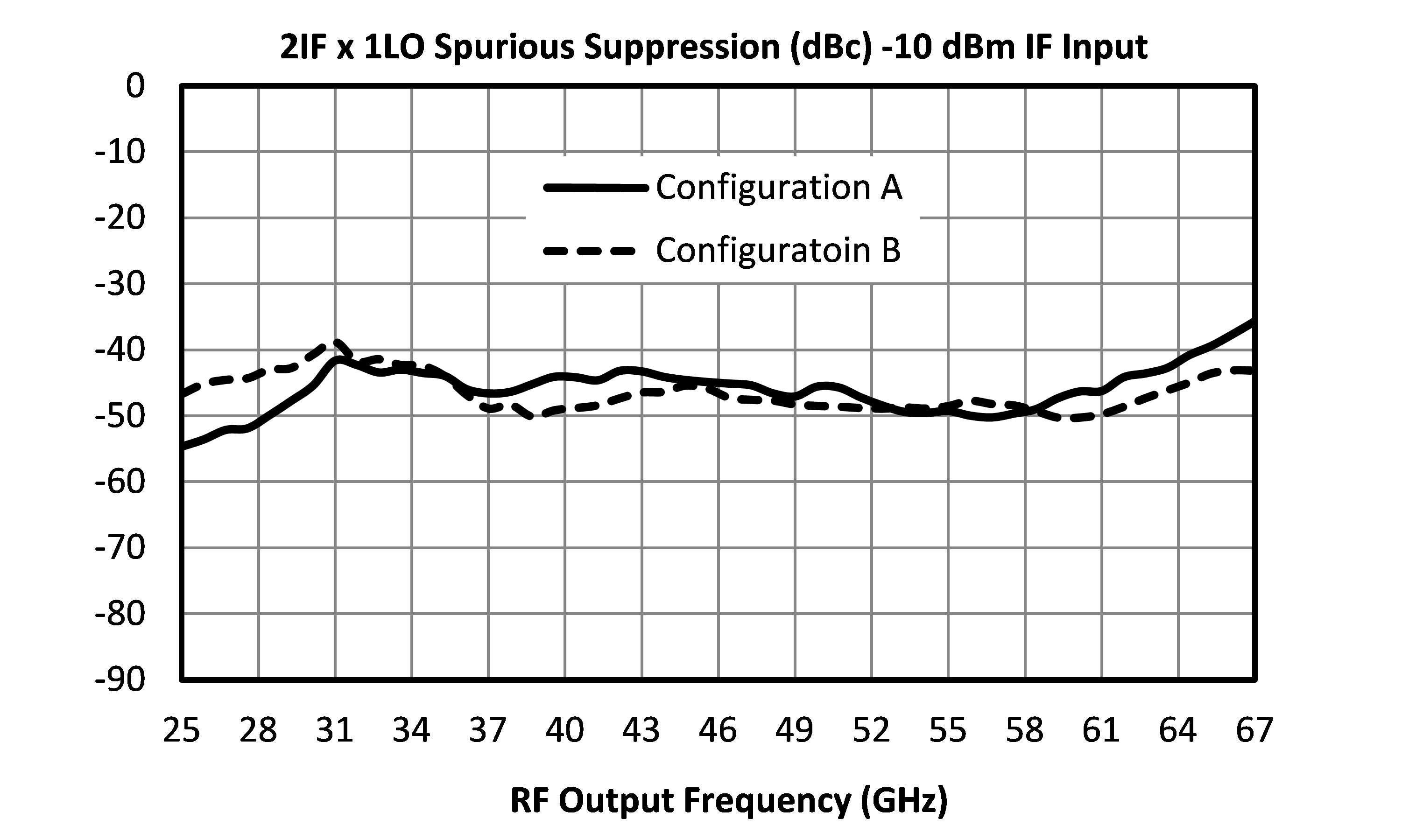
The MM1-2567LS is a passive GaAs double balanced MMIC mixer suitable for both up and down-conversion applications. As with all Marki Microwave mixers, it features excellent conversion loss, isolation and spurious performance across a broad bandwidth and in a small form factor. The MM1-2567LS is available in a connectorized package. Owing to its passive balun circuitry, the mixer can be used in two different configurations: Configuration A for highest efficiency and Configuration B for the best spurious performance and lowest LO drive.

N/A

| Part Number | Description | Package | Connectors | Green Status | Product Lifecycle | Export Classification |
|---|---|---|---|---|---|---|
| MM1-2567LS | GaAs DOUBLE-BALANCED MIXER | S | Standard | REACH RoHS | Released | EAR99 |
| MM1-2567LCH-2 | GaAs Double-Balanced Mixer | CH | - | REACH RoHS | Released | EAR99 |
| Part Number | Description | Package | Connectors | Green Status | Product Lifecycle | Export Classification |
|---|---|---|---|---|---|---|
| MM1-2567LS | GaAs DOUBLE-BALANCED MIXER | S | Standard | REACH RoHS | Released | EAR99 |
| MM1-2567LCH-2 | GaAs Double-Balanced Mixer | CH | - | REACH RoHS | Released | EAR99 |
MM1-2567LCH-2
GaAs Double-Balanced Mixer
| Revision Code | Revision Date | Comment |
|---|---|---|
| - | 2020-05-05 | Datasheet Initial Release |
| A | 2025-11-06 | MSL information added |
MM1-2567LCH-2
GaAs Double-Balanced Mixer
| Port | Function | Description | DC Equivalent Circuit |
|---|---|---|---|
| Port 1 | IF | Port 1 is DC coupled to the diodes. Blocking capacitor is optional. |  |
| Port 2 | LO | Port 2 is DC short to ground and AC matched to 50 Ohms from 25 to 67 GHz. Blocking capacitor is optional. | 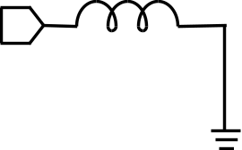 |
| Port 3 | RF | Port 3 is DC short to ground and AC matched to 50 Ohms from 25 to 67 GHz. Blocking capacitor is optional. | |
MM1-2567LCH-2
GaAs Double-Balanced Mixer
| Port | Function | Description | DC Equivalent Circuit |
|---|---|---|---|
| Port 1 | IF | Port 1 is DC coupled to the diodes. Blocking capacitor is optional. | |
| Port 2 | RF | Port 2 is DC short to ground and AC matched to 50 Ohms from 25 to 67 GHz. Blocking capacitor is optional. | |
| Port 3 | LO | Port 3 is DC short to ground and AC matched to 50 Ohms from 25 to 67 GHz. Blocking capacitor is optional. | |
MM1-2567LCH-2
GaAs Double-Balanced Mixer
| Parameter | Maximum Rating | Unit |
|---|---|---|
| Maximum Operating Temperature | 100 | °C |
| Maximum Storage Temperature | 125 | °C |
| Minimum Operating Temperature | -55 | °C |
| Minimum Storage Temperature | -65 | °C |
| Port 1 DC Current | 30 | mA |
| Port 2 DC Current | 21 | mA |
| Port 3 DC Current | 30 | mA |
| RF Power Handling (RF+LO), 100°C | 23 | dBm |
| RF Power Handling (RF+LO), 25°C | 28 | dBm |
| Parameter | Details | Rating |
|---|---|---|
| Dimensions | - | 1.38 x 1.17 mm |
| Moisture Sensitivity Level | - | MSL 1 |
| Parameter | Min | Nominal | Max | Unit |
|---|---|---|---|---|
| LO Input Power | 6 | - | 16 | - |
MM1-2567LCH-2
GaAs Double-Balanced Mixer
Specifications guaranteed from -55 to +100°C, measured in a 50Ω system
| Parameter | Port Configuration | Test Conditions | Min | Typ | Max | Unit |
|---|---|---|---|---|---|---|
| Conversion Loss | A | LO/RF=25-60 GHz IF=DC-30 GHz | - | 9 | 16 | dB |
| Input IP3 | A | LO/RF=25-67 GHz IF=DC-30 GHz LO Drive Level=10-16 dBm | - | 9 | - | dBm |
| Input P1dB | A | LO/RF=25-67 GHz IF=DC-30 GHz LO Drive Level=10-16dBm | - | 1 | - | dBm |
| LO-RF Isolation | A | - | - | 33 | - | dB |
| Conversion Loss | B | LO/RF=25-60 GHz IF=DC-30 GHz | - | 15 | 21 | dB |
| Input IP3 | B | LO/RF=25-67 GHz IF=DC-30 GHz LO Drive Level=6-12 dBm | - | 15 | - | dBm |
| Input P1dB | B | LO/RF=25-67 GHz IF=DC-30 GHz LO Drive Level=6-12 dBm | - | 5 | - | dBm |
| IF Frequency Range | - | - | 0 | - | 30 | GHz |
| LO Frequency Range | - | - | 25 | - | 67 | GHz |
| RF Frequency Range | - | - | 25 | - | 67 | GHz |
| Parameter | Port Configuration | Test Conditions | Min | Typ | Max | Unit |
|---|---|---|---|---|---|---|
| Conversion Loss | A | LO/RF=25-60 GHz IF=DC-30 GHz | - | 9 | 16 | dB |
| Input IP3 | A | LO/RF=25-67 GHz IF=DC-30 GHz LO Drive Level=10-16 dBm | - | 9 | - | dBm |
| Input P1dB | A | LO/RF=25-67 GHz IF=DC-30 GHz LO Drive Level=10-16dBm | - | 1 | - | dBm |
| LO-RF Isolation | A | - | - | 33 | - | dB |
| Conversion Loss | B | LO/RF=25-60 GHz IF=DC-30 GHz | - | 15 | 21 | dB |
| Input IP3 | B | LO/RF=25-67 GHz IF=DC-30 GHz LO Drive Level=6-12 dBm | - | 15 | - | dBm |
| Input P1dB | B | LO/RF=25-67 GHz IF=DC-30 GHz LO Drive Level=6-12 dBm | - | 5 | - | dBm |
| IF Frequency Range | - | - | 0 | - | 30 | GHz |
| LO Frequency Range | - | - | 25 | - | 67 | GHz |
| RF Frequency Range | - | - | 25 | - | 67 | GHz |
MM1-2567LCH-2
GaAs Double-Balanced Mixer
.svg)
.svg)
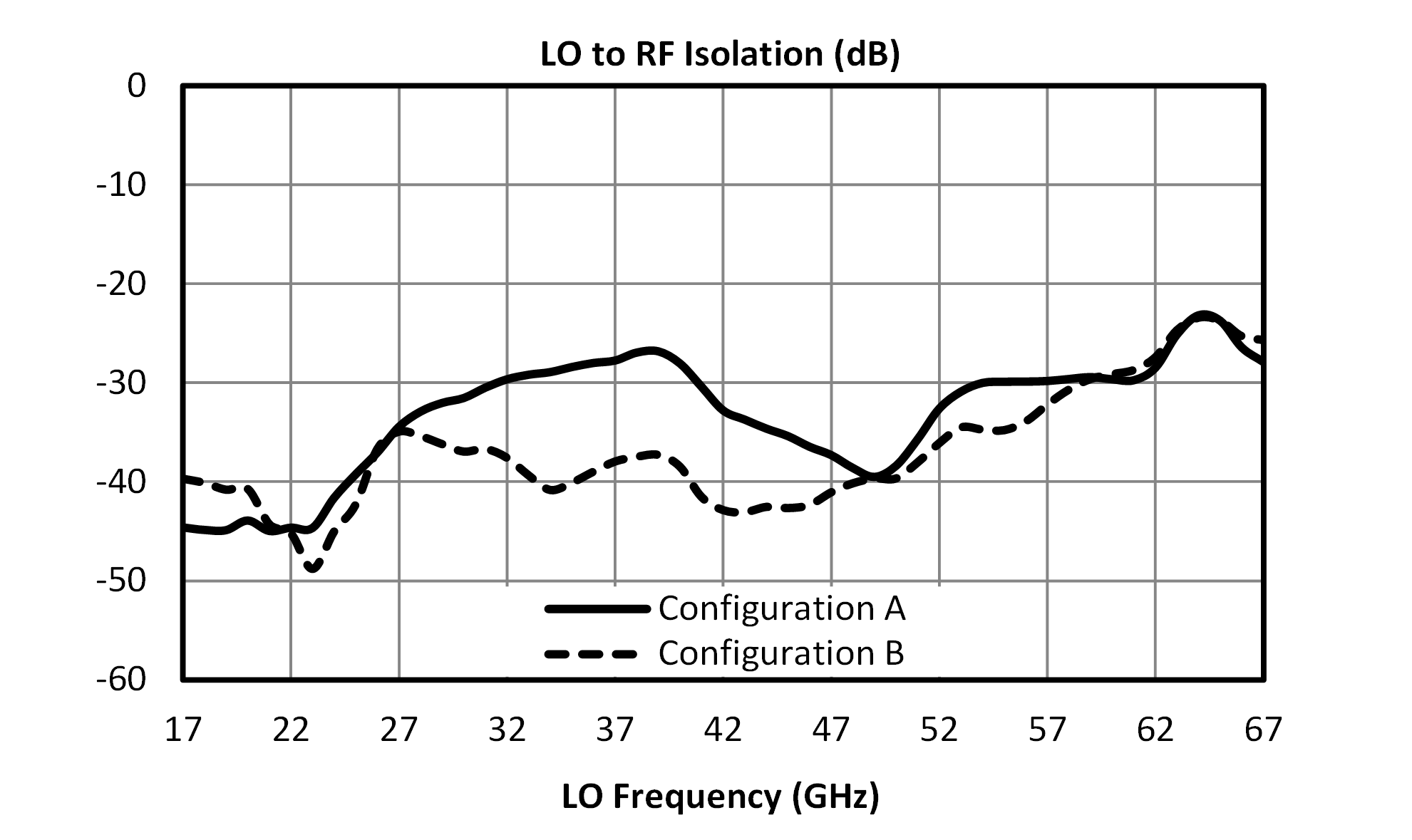
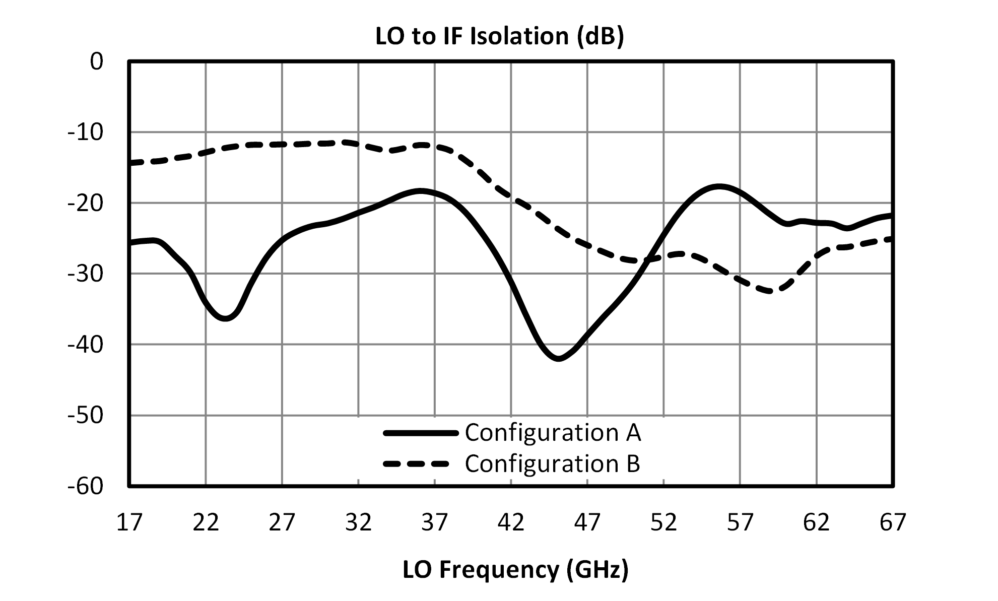
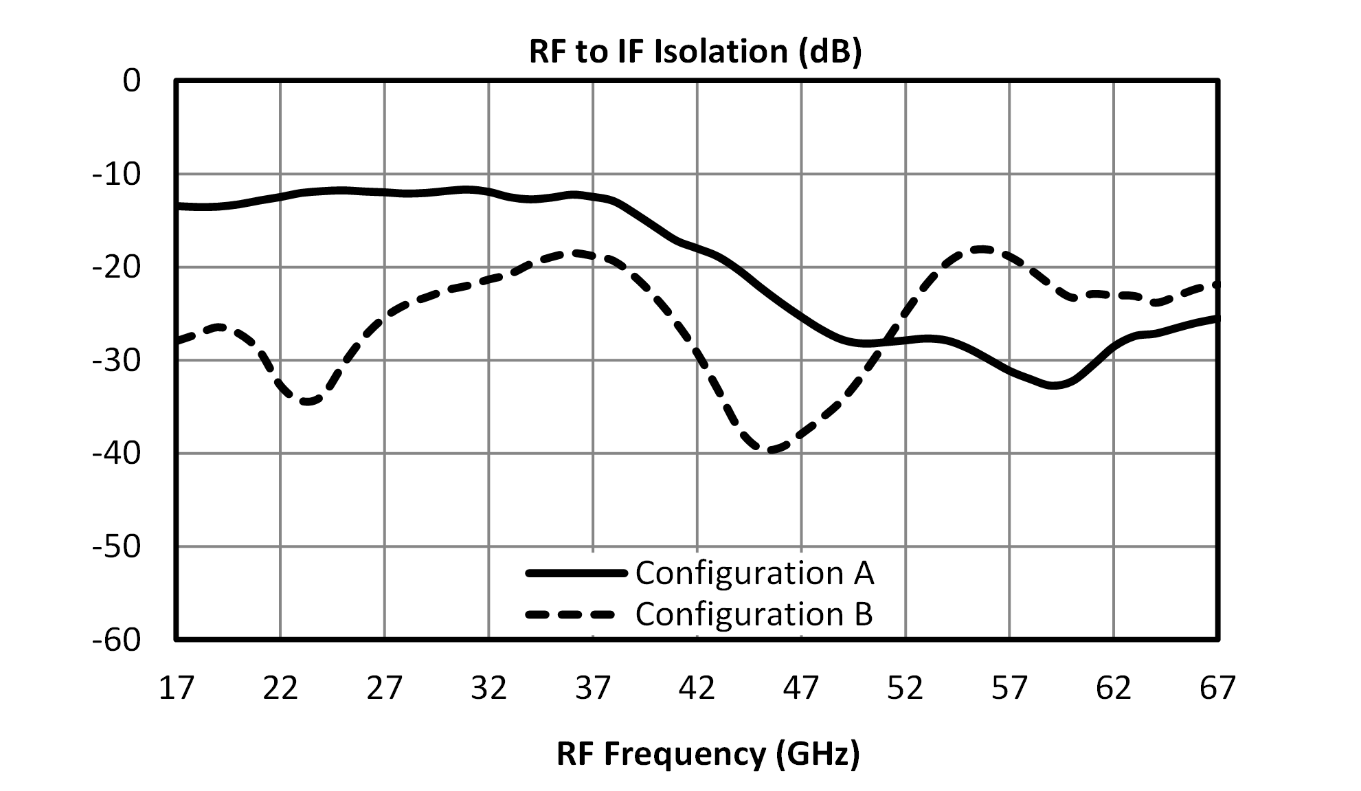
.svg)
MM1-2567LCH-2
GaAs Double-Balanced Mixer
.svg)
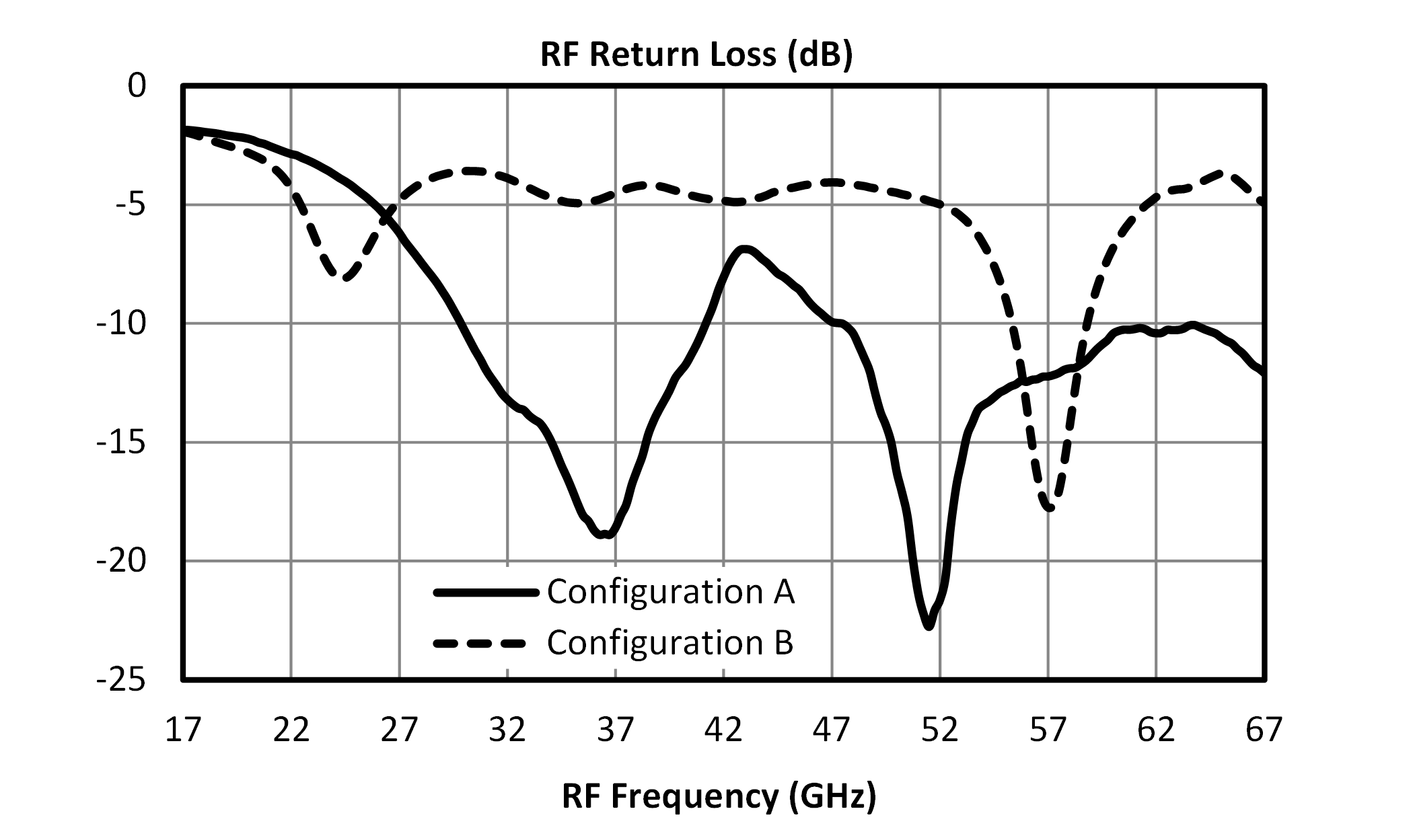
.svg)
.svg)
.svg)
.svg)
.svg)
MM1-2567LCH-2
GaAs Double-Balanced Mixer
.svg)
_-10_dBm_RF_Input.svg)
_-10_dBm_IF_Input.svg)
MM1-2567LCH-2
GaAs Double-Balanced Mixer
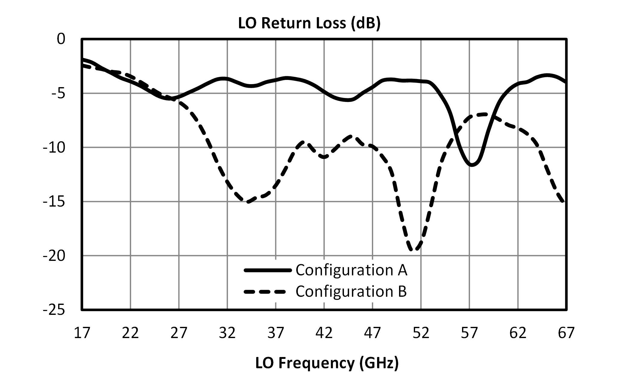
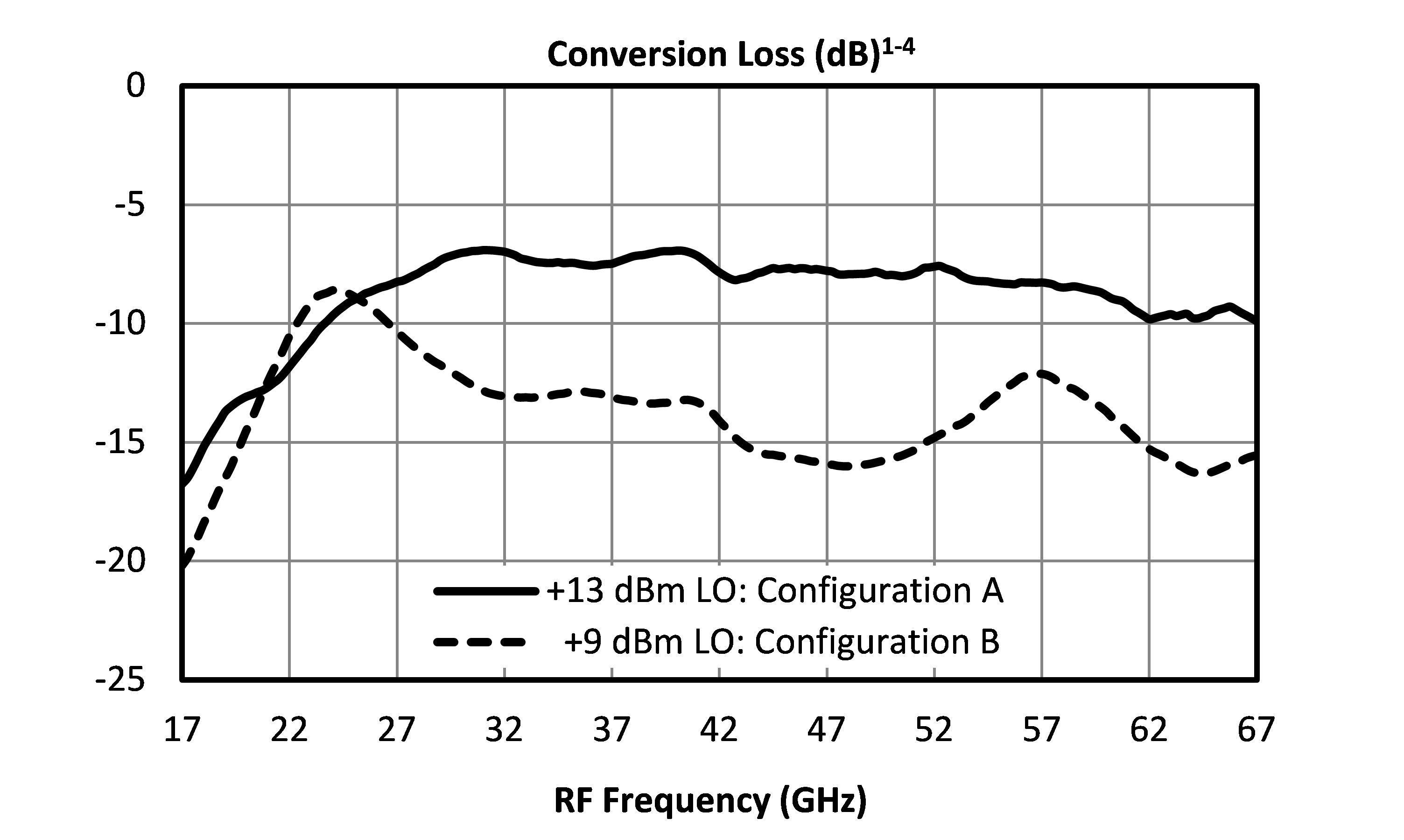
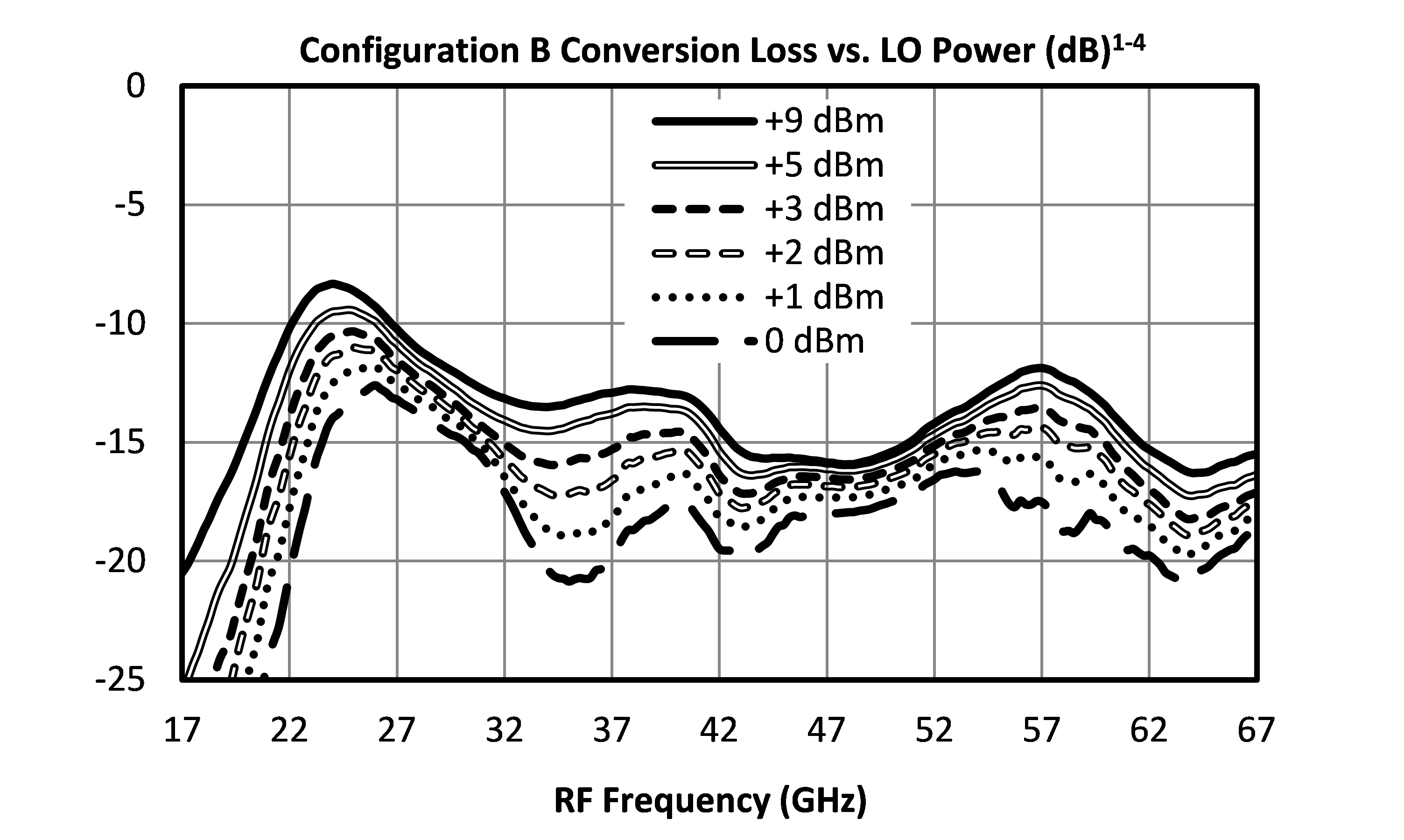
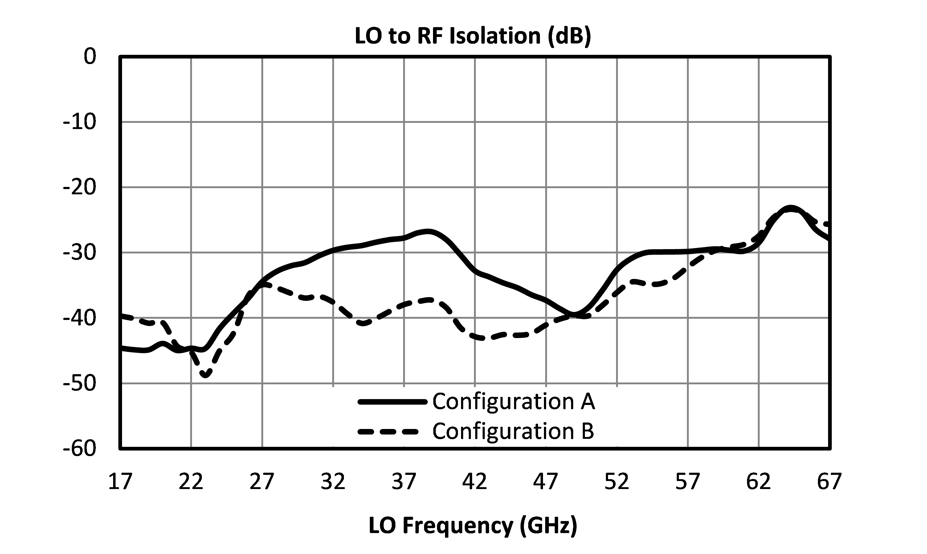
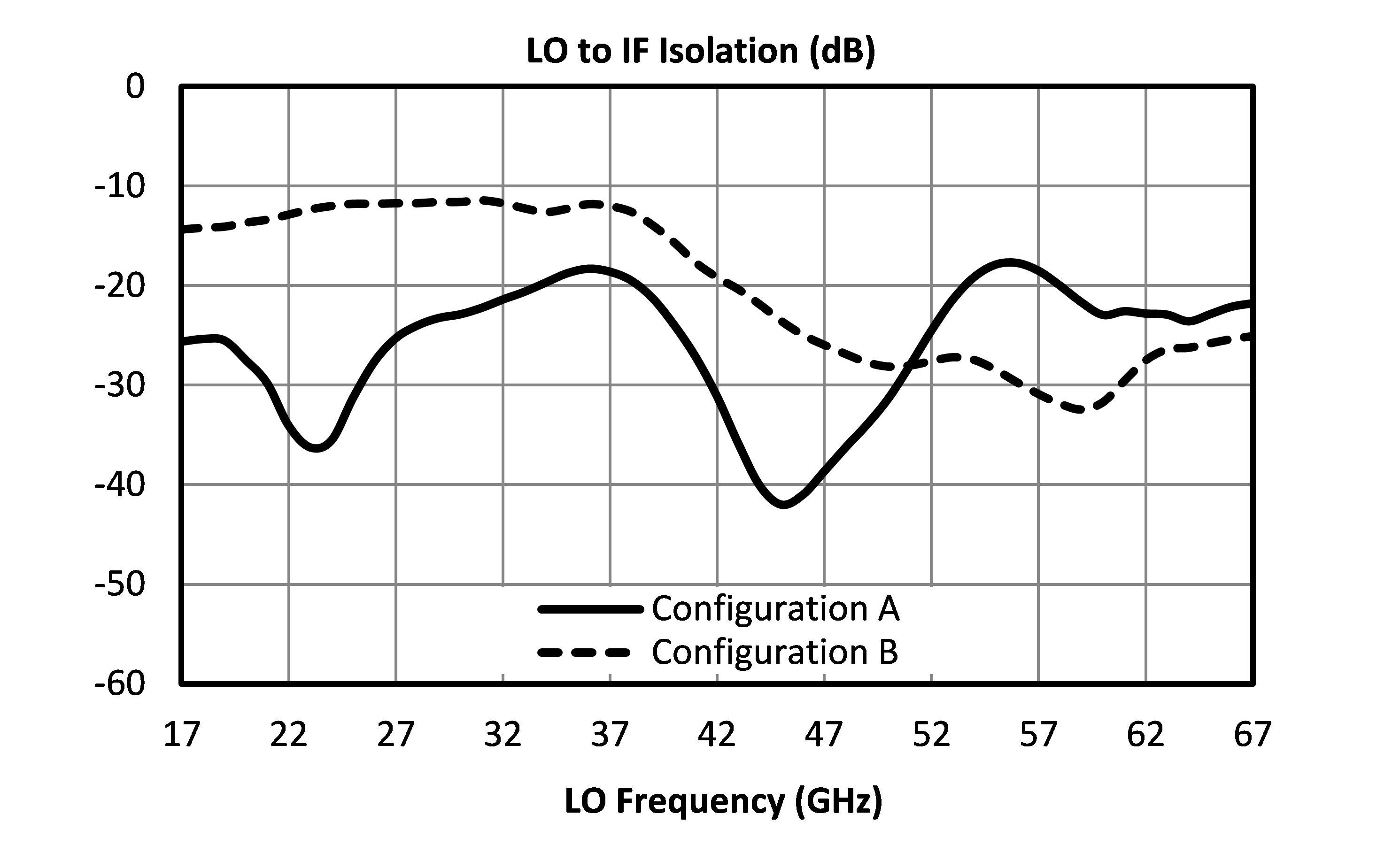
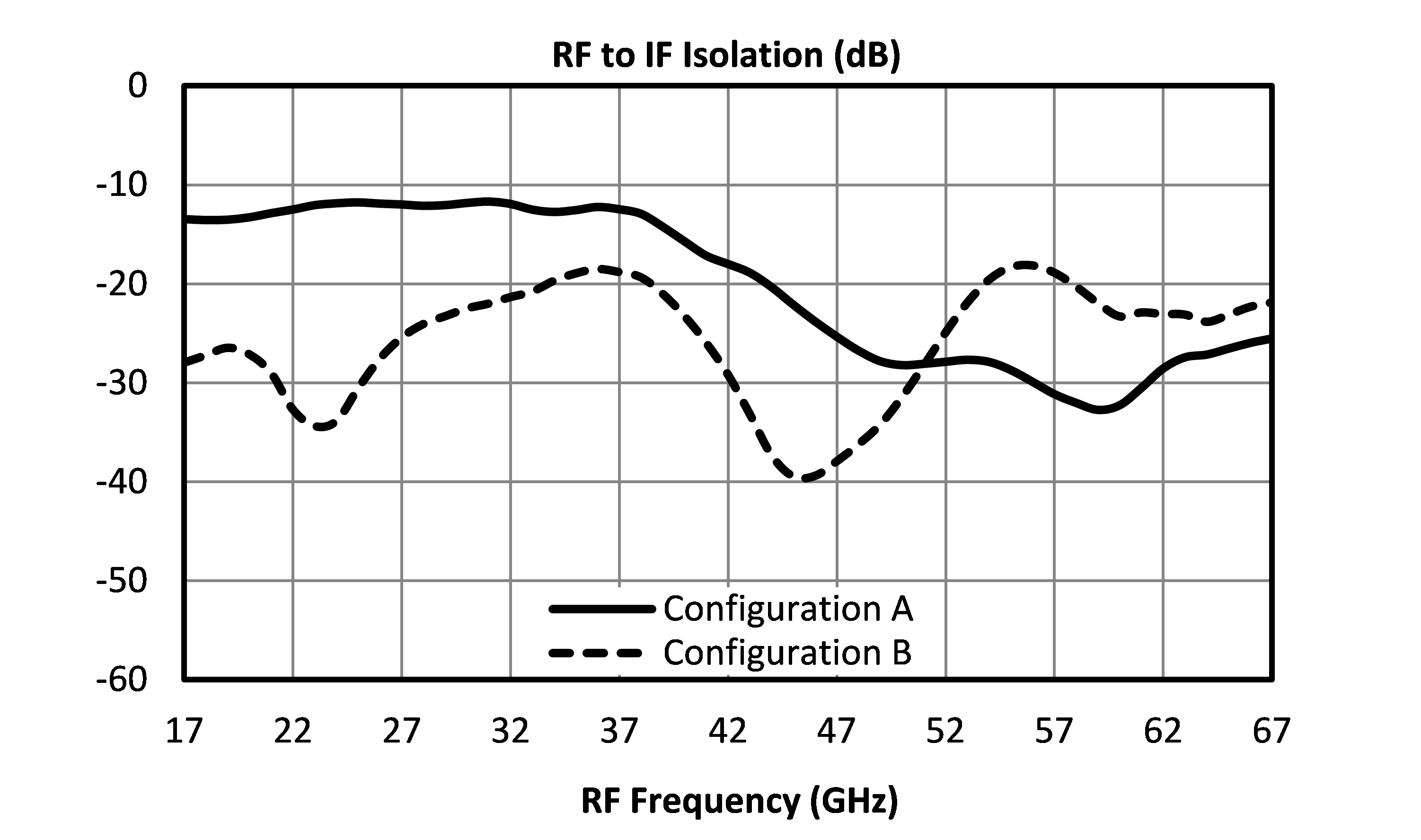
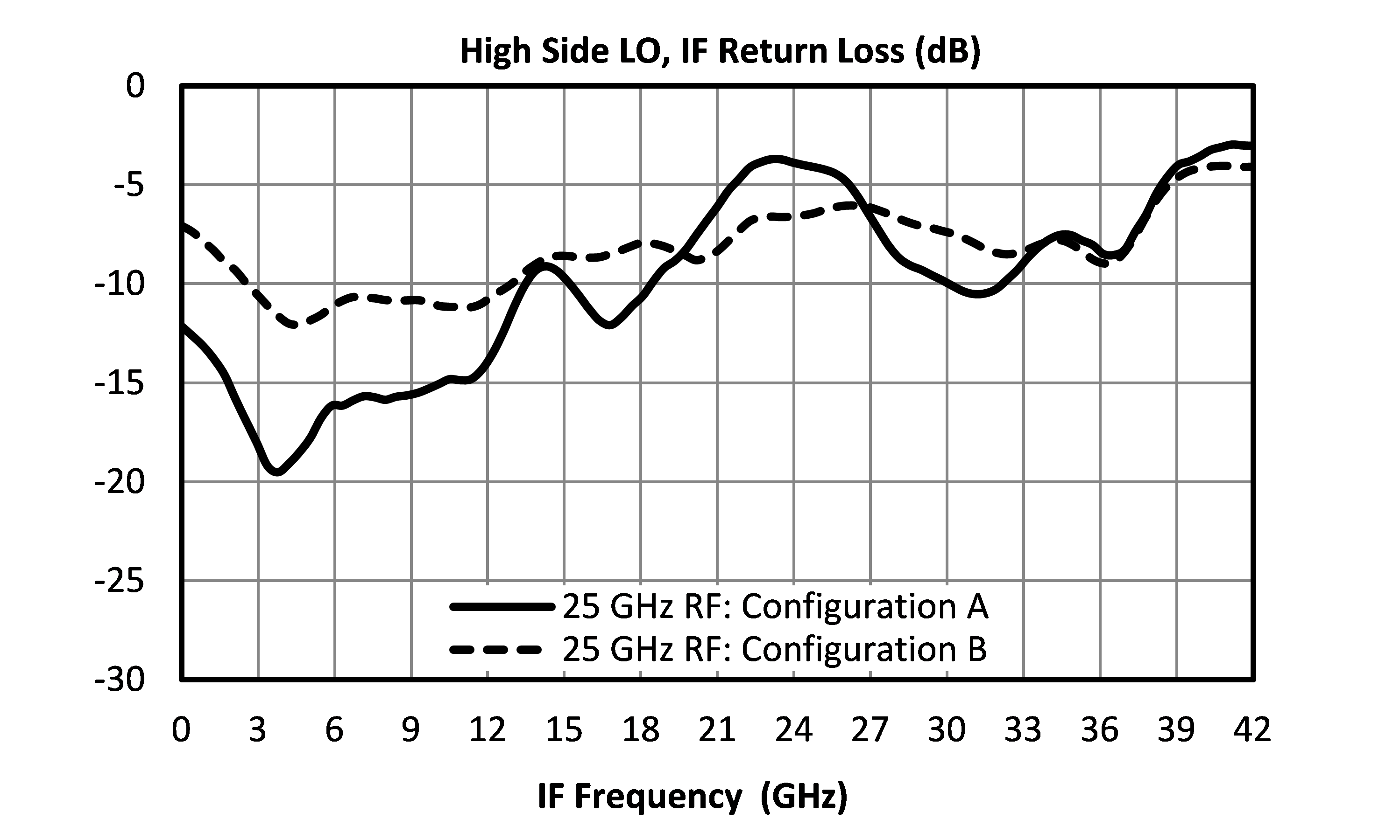
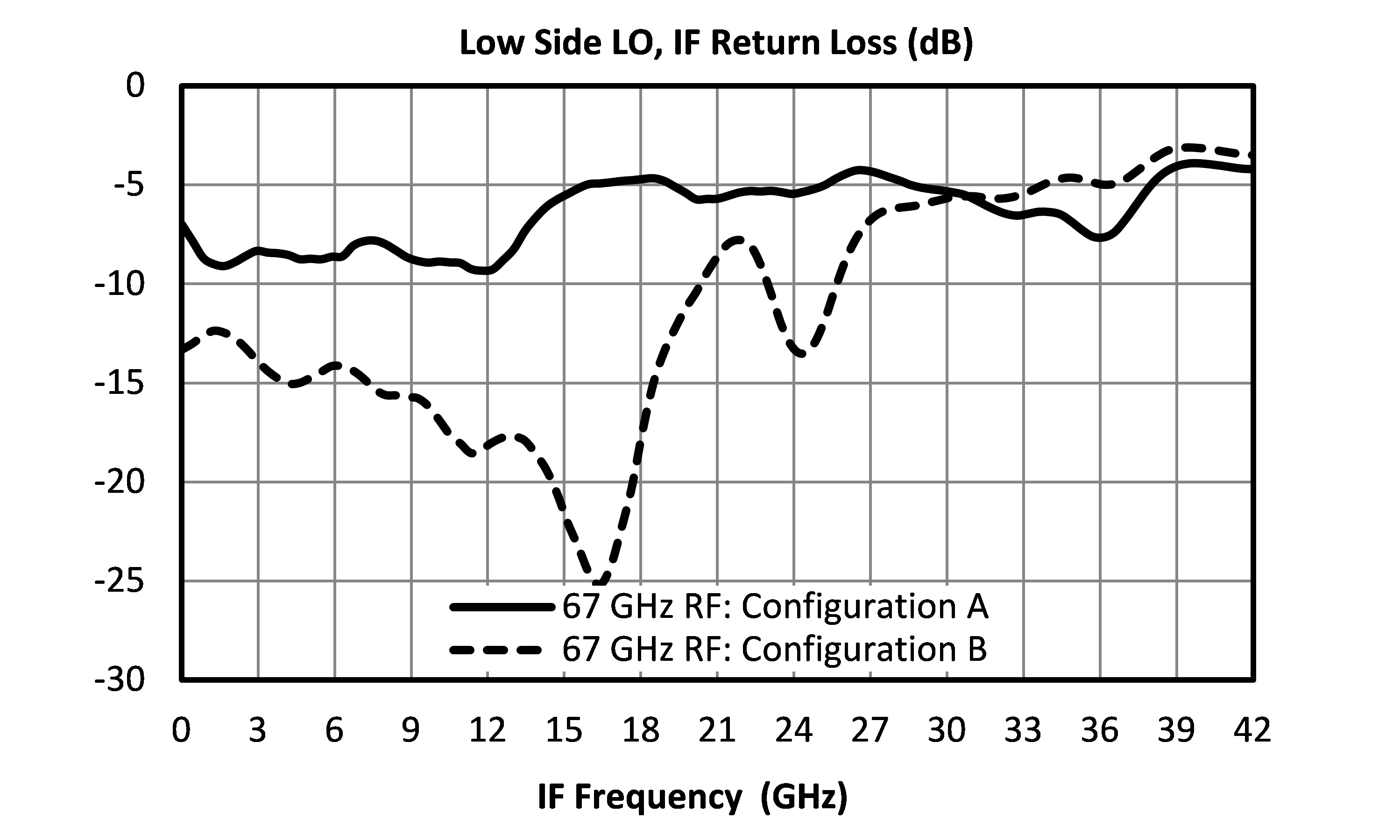
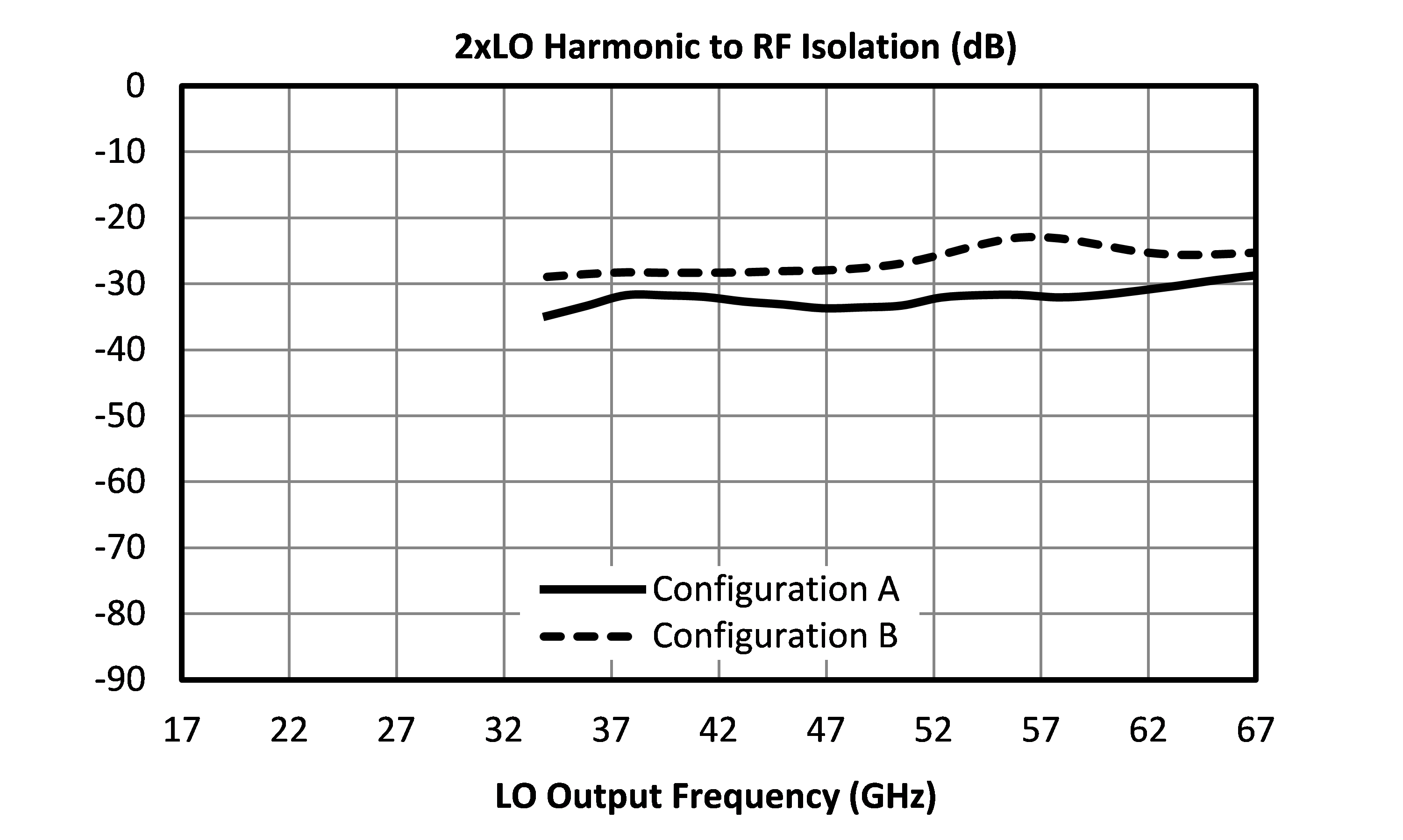
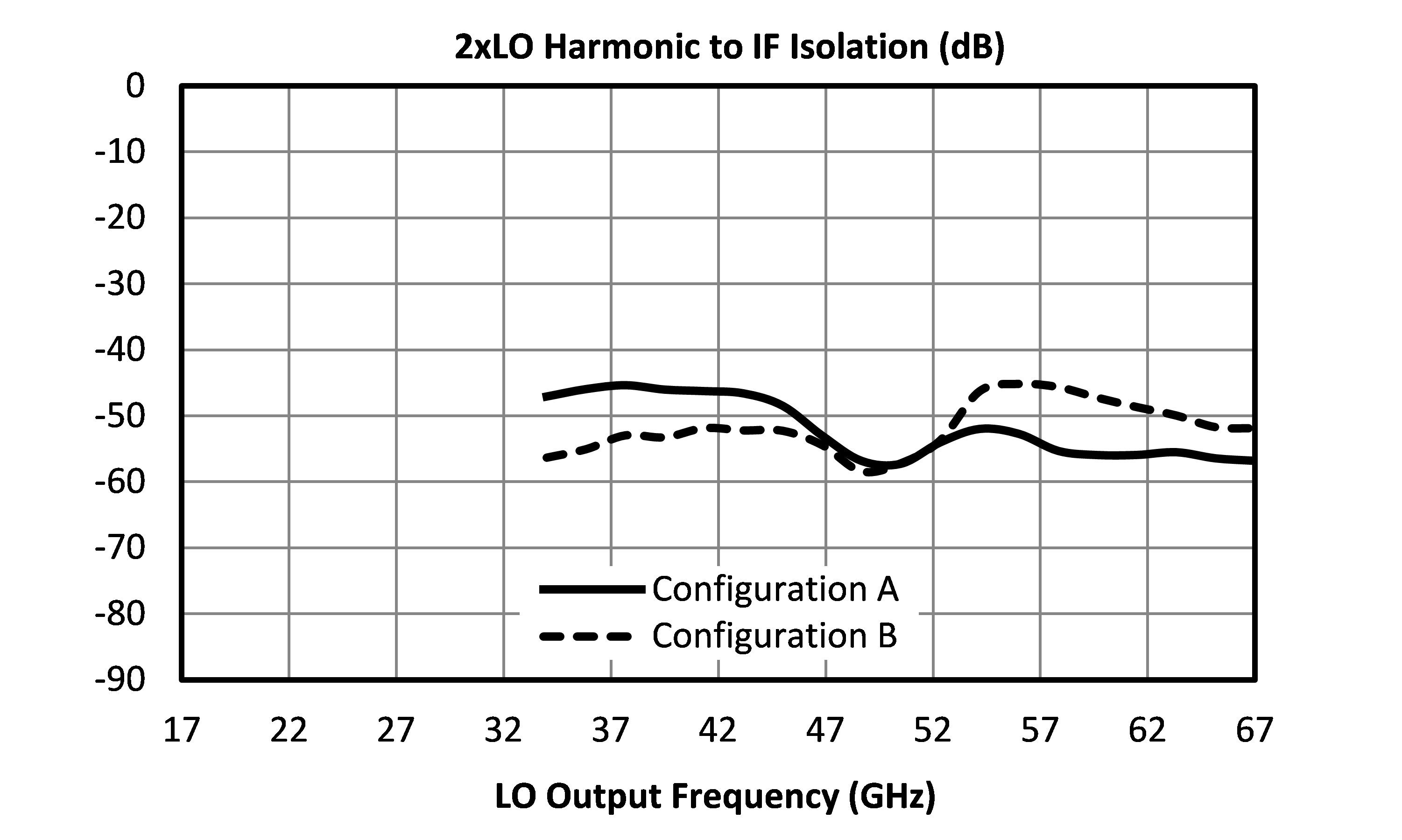
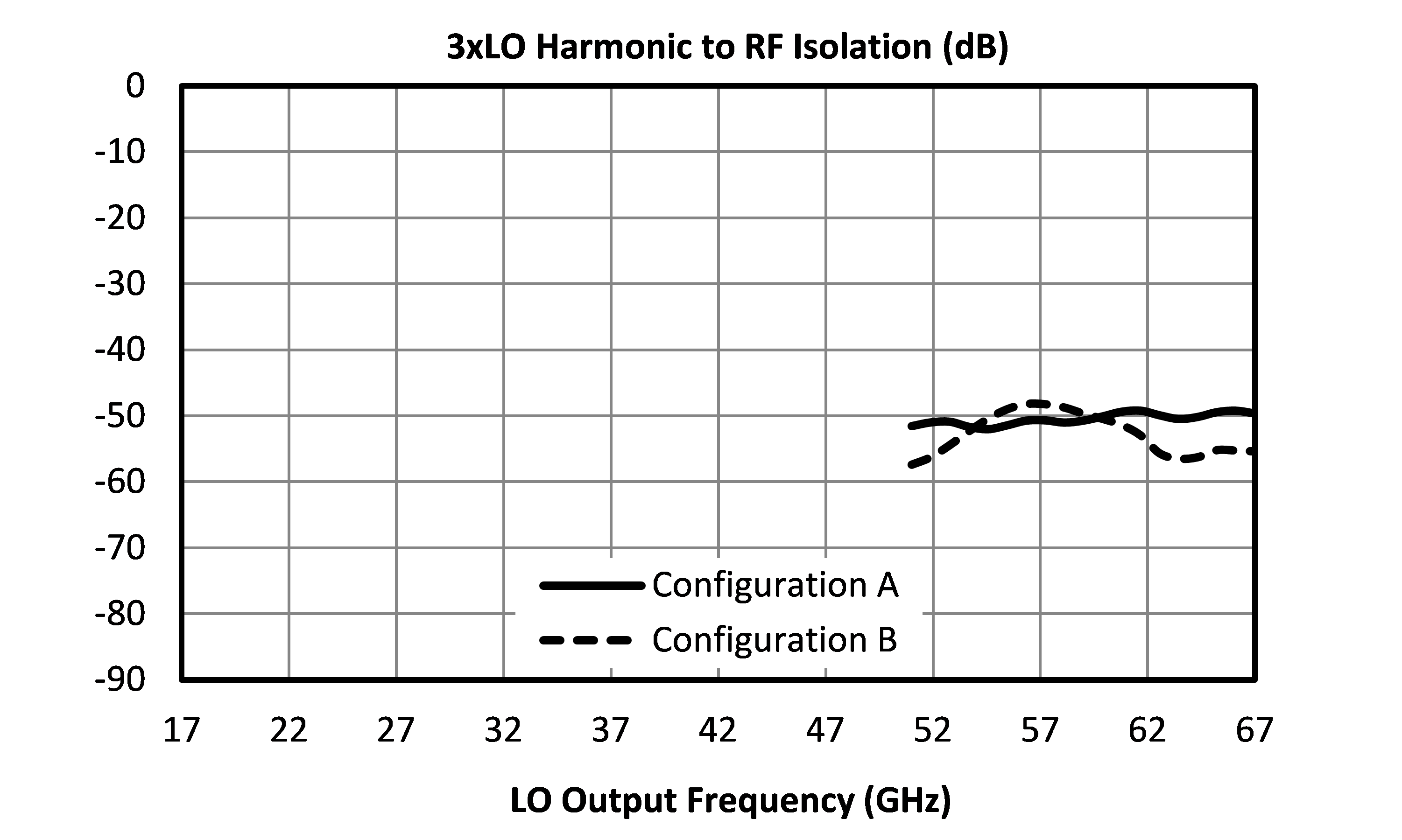
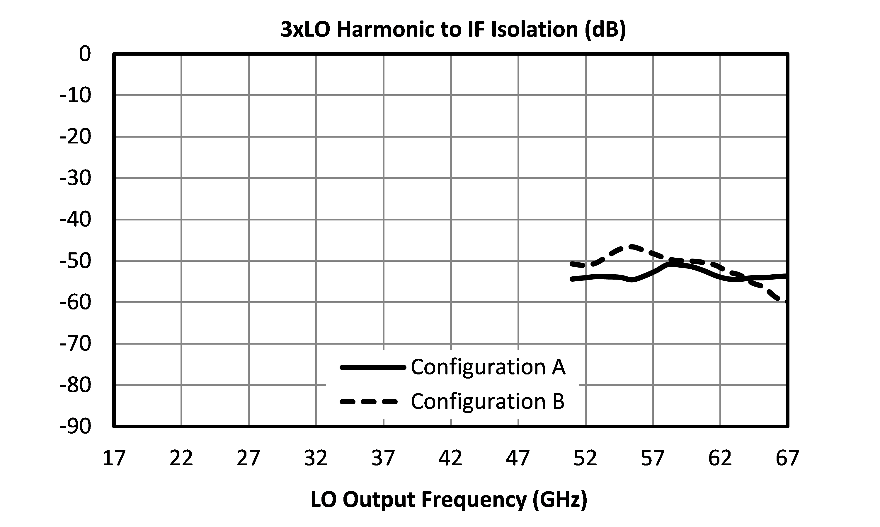
Performance plots for the connectorized module are shown for measurements where directly probed measurements of the die are unavailable. Note that the following measurements include losses from connectors and microstrip traces.


MM1-2567LCH-2
GaAs Double-Balanced Mixer
MM1-2567LCH-2
GaAs Double-Balanced Mixer
MM1-2567LCH-2
GaAs Double-Balanced Mixer