Port Diagram
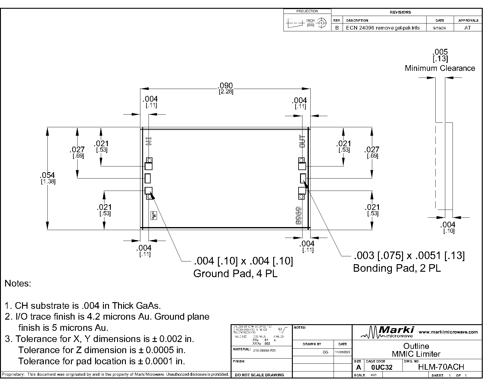
A top-down view of the HLM-70ACH's CH package outline drawing is shown below. The HLM-70ACH has the input and output ports given in Port Functions.

Sales: 408-778-9952 | General: 408-778-4200 | Fax: 408-778-4300
Sales & Customer Support: [email protected]
Tech Support: [email protected]
The HLM-70ACH is a high-power GaAs Schottky diode signal limiter. It offers low insertion loss and low return loss from DC through V band. Its high power handling makes it ideal for protecting sensitive components and for applications requiring high linearity.
N/A

| Part Number | Description | Package | Green Status | Product Lifecycle | Export Classification |
|---|---|---|---|---|---|
| HLM-70ACH | DC - 70GHz High Frequency Limiter | CH | RoHS REACH | Released | EAR99 |
| Part Number | Description | Package | Green Status | Product Lifecycle | Export Classification |
|---|---|---|---|---|---|
| HLM-70ACH | DC - 70GHz High Frequency Limiter | CH | RoHS REACH | Released | EAR99 |
HLM-70ACH
DC - 70GHz High Frequency Limiter
| Revision Code | Revision Date | Comment |
|---|---|---|
| - | 2024-04-03 | Datasheet Initial Release |
| A | 2026-06-02 | Added Recovery Time and Spike Leakage |
HLM-70ACH
DC - 70GHz High Frequency Limiter
A top-down view of the HLM-70ACH's CH package outline drawing is shown below. The HLM-70ACH has the input and output ports given in Port Functions.
| Port | Function | Description | DC Equivalent Circuit |
|---|---|---|---|
| GND | Ground | CH package ground path is provided through the substrate and ground bond pads. |  |
| IN | Input | IN is the RF input port and is diode connected for the CH package. |  |
| OUT | Output | OUT is the RF output port and is diode connected for the CH package. | |
HLM-70ACH
DC - 70GHz High Frequency Limiter
| Parameter | Maximum Rating | Unit |
|---|---|---|
| Maximum Operating Temperature | 100 | °C |
| Maximum Storage Temperature | 125 | °C |
| Minimum Operating Temperature | -55 | °C |
| Minimum Storage Temperature | -65 | dB |
| RF Power Handling, CW @ 10 GHz, 25°C | 1 | W |
RF Power Handling represents an instantaneous, catastrophic limit and it isn’t derated for frequency, temperature, pulse conditions, or unit to unit variation.
| Parameter | Details | Rating |
|---|---|---|
| Dimensions | - | 2.28x1.38mm |
HLM-70ACH
DC - 70GHz High Frequency Limiter
The electrical specifications apply at TA=+25°C in a 50Ω system. Data is measured with 3 wirebonds. Min and Max limits are guaranteed at TA=+25°C. All bare die are 100% visually inspected and RF performance is guaranteed by sample testing.
| Parameter | Test Conditions | Minimum Frequency (GHz) | Maximum Frequency (GHz) | Min | Typ | Max | Unit |
|---|---|---|---|---|---|---|---|
| Spike Leakage | - | - | - | - | 0.1 | - | erg |
| Recovery Time | - | - | - | - | 8 | - | ns |
| Flat Leakage | - | 40 | 40 | - | 9 | - | dBm |
| Flat Leakage | - | 30 | 30 | - | 9.5 | - | dBm |
| Flat Leakage | - | 20 | 20 | - | 10.5 | - | dBm |
| Flat Leakage | - | 50 | 50 | - | 9 | - | dBm |
| Insertion Loss | - | 0 | 70 | - | 0.8 | 2.7 | dB |
| Return Loss | - | 0 | 70 | - | 19 | - | dB |
HLM-70ACH
DC - 70GHz High Frequency Limiter
Data is measured with 3 wirebonds.


HLM-70ACH
DC - 70GHz High Frequency Limiter


HLM-70ACH
DC - 70GHz High Frequency Limiter