Rev: B | Copyright © 2017, 2019, 2023 Marki Microwave LLC.

General Description

The MEQ10-60A is a passive MMIC equalizer. It is a positive gain slope equalizer designed to pass DC to 60GHz. Equalization can be applied to reduce low pass filtering effects in both RF/microwave and high speed digital systems. Passive GaAs MMIC technology allows production of smaller equalizer constructions that replace larger form factor circuit board constructions. Better IC tolerances allow for less unit to unit variation that traditionally etched circuits have. Low unit to unit variation allow for accurate simulations using the provided S2P file taken from measured production units.

Features

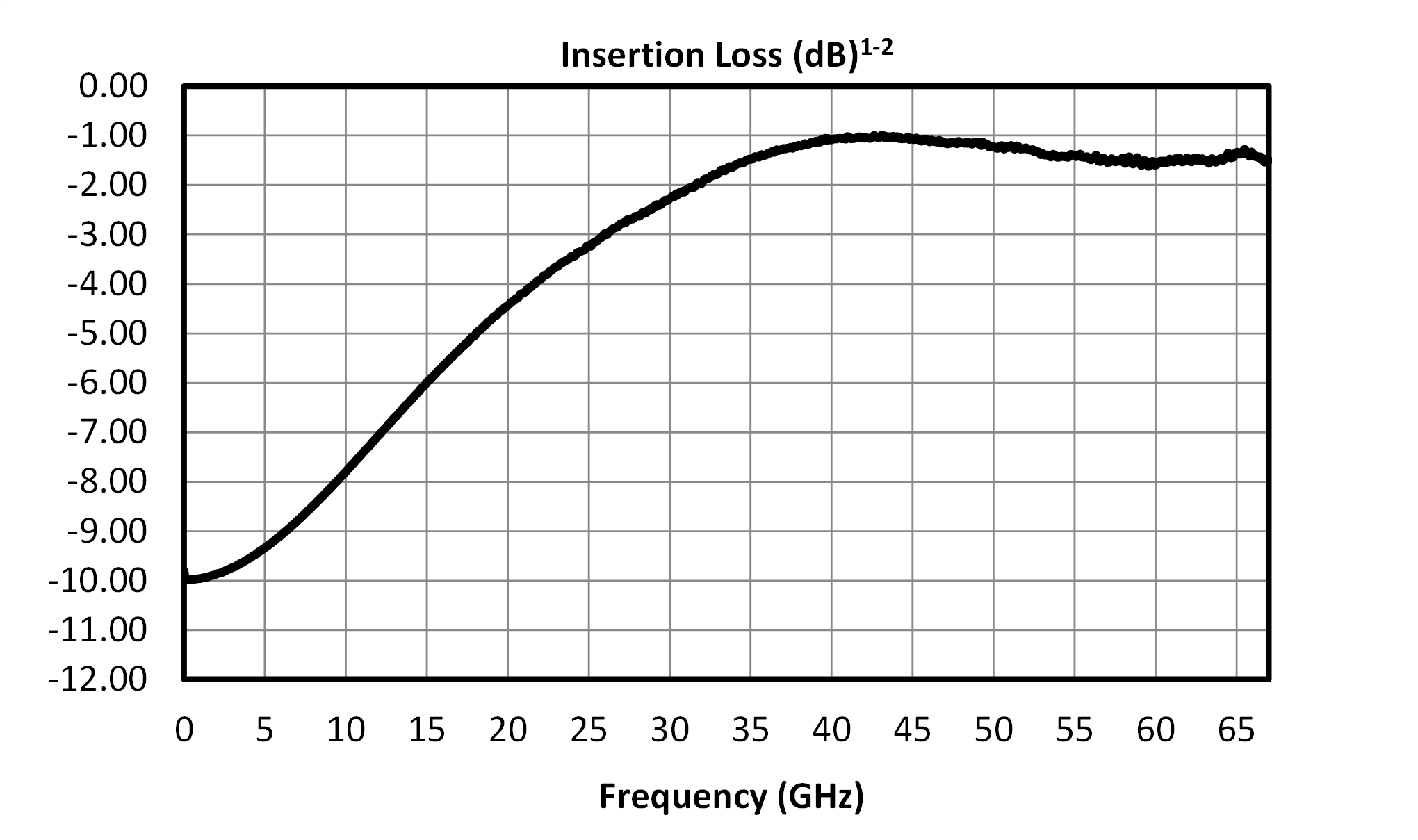
  • Insertion loss typically 1.6dB at 60GHz
  • 10dB low frequency attenuation
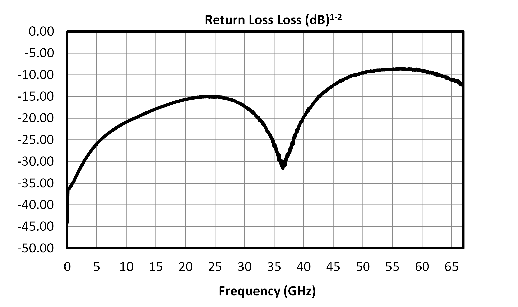
  • Excellent return loss
  • Broadband Operation
  • RoHS Compliant

Functional Block Diagram

Block Diagram
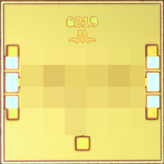
Photo of MEQ10-60ACH

Electrical Performance Summary

ParameterTypUnit
Frequency Range0 to 60GHz
Return Loss 15dB
Insertion Loss 1dB
Insertion Loss at DC 10dB

Summary only – refer to the Electrical Specifications, Absolute Maximum Ratings, and Recommended Operating Range tables for complete details.

Part Ordering Options

Part NumberDescriptionPackageGreen StatusProduct LifecycleExport Classification
MEQ10-60ACHPassive MMIC 60GHz EqualizerCH

REACH

RoHS

ReleasedEAR99

Table Of Contents

Typical Performance Plots

Insertion Loss vs Frequency graph for MEQ10-60ACH
Return Loss vs Frequency graph for MEQ10-60ACH
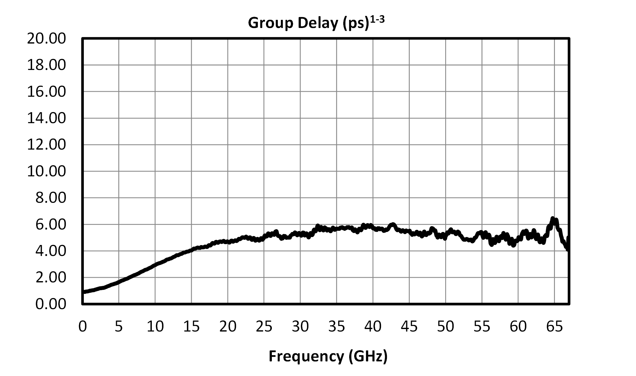
Group Delay vs Frequency graph for MEQ10-60ACH

Specifications

Electrical Specifications

Specifications guaranteed for +25°C for chip (CH) package, measured in a 50Ω system.

ParameterTest ConditionsMinimum
Frequency
(GHz)
Maximum
Frequency
(GHz)
MinTypMaxUnit
Frequency Range-0 60---GHz
Insertion Loss -60 60-1.62.5dB
Insertion Loss -40 40-1-dB
Insertion Loss at DC -0 0-10-dB
Return Loss -40 60-8-dB
Return Loss -0 401215-dB
Return Loss -60 67-10-dB
Impedance -- --50-Ω
Insertion Loss -67 67-1.5-dB

Absolute Maximum Ratings

ParameterMaximum RatingUnit
Maximum Spec Guaranteed Operating Temperature 125°C
Maximum Storage Temperature 125°C
Minimum Spec Guaranteed Operating Temperature -65°C
Minimum Storage Temperature -65°C
Operating Temperature 25°C

Package Information

ParameterDetailsRating
ESD250 to < 500 VoltsHBM Class 1A
Dimensions-1.25 x 1.25 mm

Port Configuration and Functions

Port Diagram

Diagram of the port configuration for MEQ10-60ACH

Port Functions

PortFunctionDescriptionDC Equivalent
Circuit
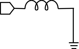
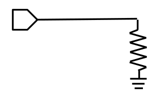
Port 1Input/Output Port 1 is DC connected to ground through a resistor. DC block is required if voltage present.Equivalent circuit for the Input/Output
Port 2Input/Output Port 2 is DC connected to ground through a resistor. DC block is required if voltage present. Equivalent circuit for the Input/Output

Die Mounting Recommendations

Mounting and Bonding Recommendations

Marki MMICs should be attached directly to a ground plane with conductive epoxy. The ground plane electrical impedance should be as low as practically possible. This will prevent resonances and permit the best possible electrical performance. Datasheet performance is only guaranteed in an environment with a low electrical impedance ground.

Mounting - To epoxy the chip, apply a minimum amount of conductive epoxy to the mounting surface so that a thin epoxy fillet is observed around the perimeter of the chip. Cure epoxy according to manufacturer instructions.

Wire Bonding - Ball or wedge bond with 0.025 mm (1 mil) diameter pure gold wire. Thermosonic wirebonding with a nominal stage temperature of 150 °C and a ball bonding force of 40 to 50 grams or wedge bonding force of 18 to 22 grams is recommended. Use the minimum level of ultrasonic energy to achieve reliable wirebonds. Wirebonds should be started on the chip and terminated on the package or substrate. All bonds should be as short as possible <0.31 mm (12 mils).

Circuit Considerations – 50 Ω transmission lines should be used for all high frequency connections in and out of the chip. Wirebonds should be kept as short as possible, with multiple wirebonds recommended for higher frequency connections to reduce parasitic inductance. In circumstances where the chip more than .001” thinner than the substrate, a heat spreading spacer tab is optional to further reduce bondwire length and parasitic inductance.

Handling Precautions

General Handling: Chips should be handled with a vacuum collet when possible, or with sharp tweezers using well trained personnel. The surface of the chip is fragile and should not be contacted if possible.

Static Sensitivity: GaAs MMIC devices are subject to static discharge, and should be handled, assembled, tested, and transported only in static protected environments.

Cleaning and Storage: Do not attempt to clean the chip with a liquid cleaning system or expose the bare chips to liquid. Once the ESD sensitive bags the chips are stored in are opened, chips should be stored in a dry nitrogen atmosphere.

Bonding Diagram

Me Q10 60 Ach Bonding Diagram

Mechanical Data

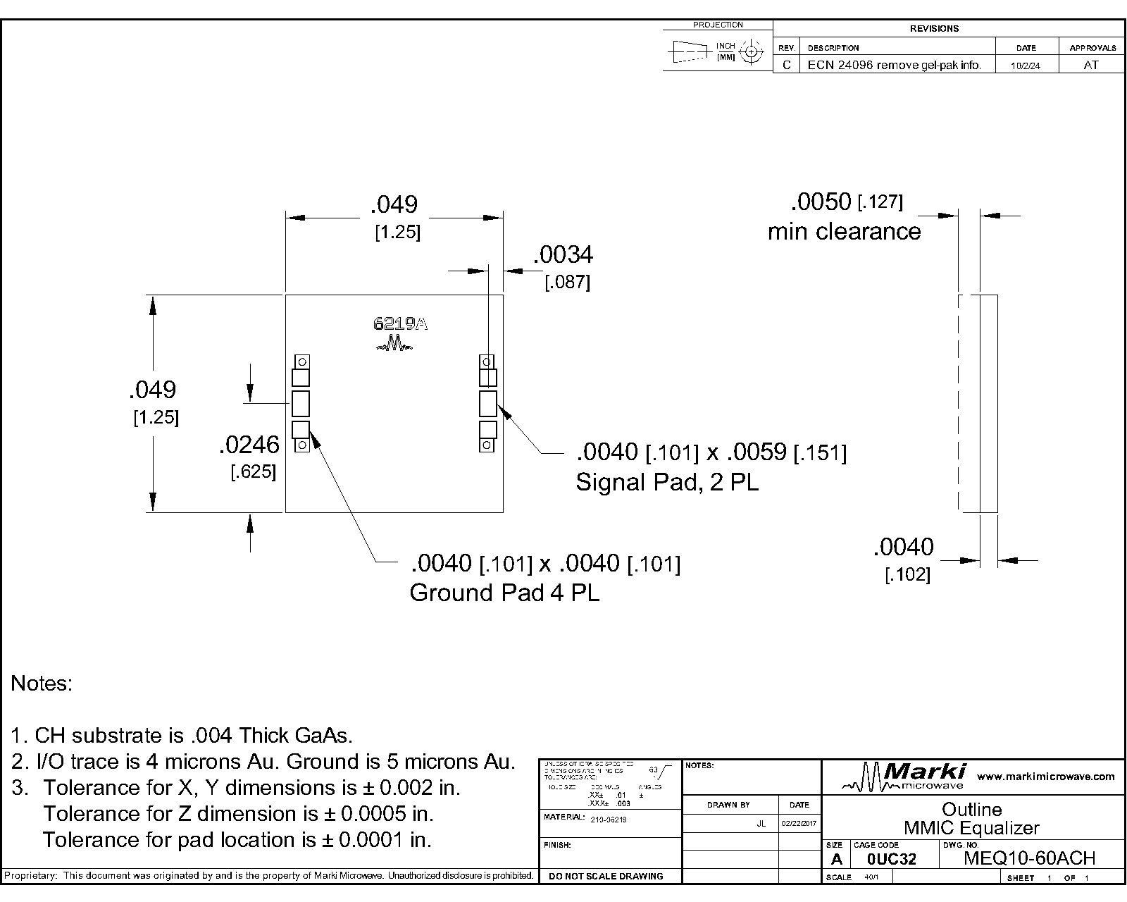
Outline Drawing

Download : Outline 2D Drawing

Outline Drawing

Revision History

Revision CodeRevision DateComment
-2017-01-01Initial Release
A2019-03-01Added ESD rating
B2023-01-01Added Extended Performance to 67 GHz

Notes

DATA SHEET NOTES:

  1. Equalizer is symmetrical. Reverse measurement is equivalent to forward measurement.
  2. Measured typical data available for integrated circuit only.
  3. Group delay calculated using wrapped phase response.
  4. Specifications are subject to change without notice. Contact Marki Microwave for the most recent specifications and data sheets.
  5. Catalog circuits are continually improved. Configuration control requires custom model numbers and specifications.

Note: Exposure to maximum rating conditions for extended periods may reduce device reliability. There is no damage to device with only one parameter set at the limit and all other parameters set at or below their nominal value. Exceeding any of the limits listed here may result in permanent damage to the device.

DISCLAIMER

MARKI MICROWAVE, LLC., (“MARKI”) PROVIDES TECHNICAL SPECIFICATIONS AND DATA (INCLUDING DATASHEETS), APPLICATION OR OTHER DESIGN ADVICE, WEB TOOLS, AND OTHER INFORMATION AND RESOURCES “AS IS” AND WITH ALL FAULTS. MARKI DISCLAIMS ALL WARRANTIES, EXPRESS OR IMPLIED, INCLUDING, WITHOUT LIMITATION, ANY IMPLIED WARRANTIES OF MERCHANTABILITY, FITNESS FOR A PARTICULAR PURPOSE, OR NON-INFRINGEMENT.

These resources are intended for developers skilled in the art designing with Marki products. You are solely responsible for (1) selecting the appropriate products for your application, (2) designing, validating, and testing your application, and (3) ensuring your application meets applicable standards and other requirements. Marki makes no guarantee regarding the suitability of its products for any particular purpose, nor does Marki assume any liability whatsoever arising out of your use or application of any Marki product.

Marki grants you permission to use these resources only for development of an application that uses Marki products. Other reproduction or use of these resources is strictly prohibited. No license is granted to any other Marki intellectual property or to any third-party intellectual property. Marki reserves the right to make changes to the product(s) or information contained herein without notice.

MARKI MICROWAVE, M wave logo, FastSwitch, and T3 MIXER are trademarks or registered trademarks of Marki Microwave, LLC. All other trademarks used are the property of their respective owners.

© 2017, 2019, 2023, Marki Microwave, LLC