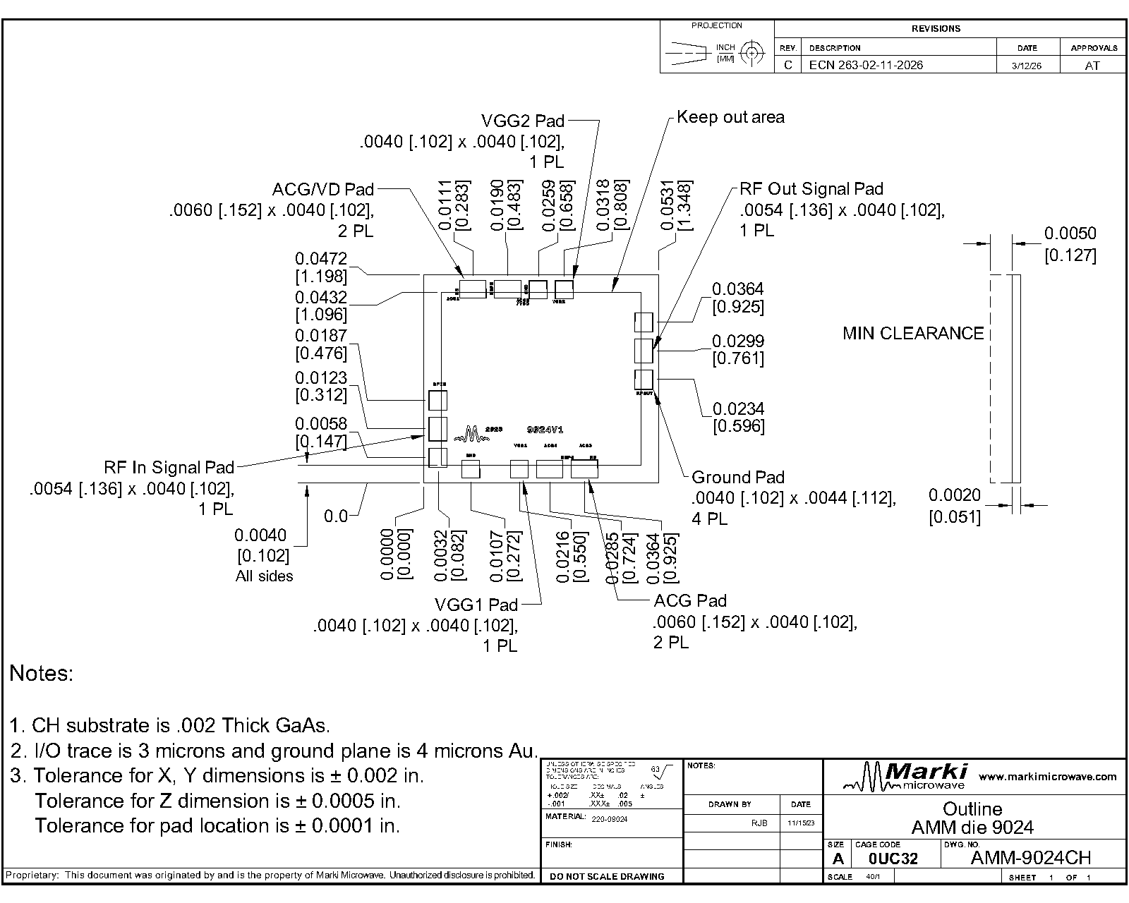
Port Diagram
The port diagram of the AMM-9024CH is shown below.


Sales: 408-778-9952 | General: 408-778-4200 | Fax: 408-778-4300
Sales & Customer Support: [email protected]
Tech Support: [email protected]
The AMM-9024CH is a broadband GaAs MMIC distributed amplifier enabling operation over a DC-70 GHz bandwidth. The amplifier features an 11 dB flat gain response, excellent return losses, and a low 2.5 dB noise figure. Available as a wire-bondable die.


| Part Number | Description | Package | Green Status | Product Lifecycle | Export Classification |
|---|---|---|---|---|---|
| AMM-9024CH | DC- 70GHz, Broadband Distributed Amplifier | CH | REACH RoHS | Released | 3A001.b.2.d |
| AMM-9024KGD | Known Good Die, DC- 70GHz, Broadband Distributed Amplifier | CH | REACH RoHS | Released | 3A001.b.2.d |
| Part Number | Description | Package | Green Status | Product Lifecycle | Export Classification |
|---|---|---|---|---|---|
| AMM-9024CH | DC- 70GHz, Broadband Distributed Amplifier | CH | REACH RoHS | Released | 3A001.b.2.d |
| AMM-9024KGD | Known Good Die, DC- 70GHz, Broadband Distributed Amplifier | CH | REACH RoHS | Released | 3A001.b.2.d |
AMM-9024CH
DC- 70GHz, Broadband Distributed Amplifier
| Revision Code | Revision Date | Comment |
|---|---|---|
| - | 2024-02-01 | Initial Datasheet Release |
| A | 2024-10-03 | Absolute Maximum RF Input Power limit increased to +20dBm. |
AMM-9024CH
DC- 70GHz, Broadband Distributed Amplifier
The port diagram of the AMM-9024CH is shown below.
AMM-9024CH
DC- 70GHz, Broadband Distributed Amplifier
| Port | Function | Description | DC Equivalent Circuit |
|---|---|---|---|
| ACG1 | AC Ground | This pad should be attached to an off-chip bypass capacitor. The recommended bypassing for this pad is 0.1uF. Do not ground this pad. | - |
| ACG3 | AC Ground | This pad should be attached to an off-chip bypass capacitor. The recommended bypassing for this pad is 0.1uF. Do not ground this pad. | - |
| ACG4 | AC Ground | This pad should be attached to an off-chip bypass capacitor. The recommended bypassing for this pad is 0.1uF. Do not ground this pad. | - |
| GND | Ground | Bottom side of the die must be connected to a DC/RF ground with high thermal and electrical conductivity. There is no need to bond to the Gnd pads on the top of the die. |  |
| RF In | RF Input | The amplifier’s RF Input pad, this pad requires an external blocking capacitor as shown in the application schematic. This pad is internally matched to 50 Ohms. | 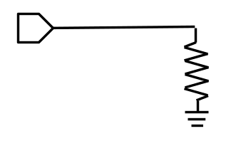 |
| RF Out | RF Output | The amplifier’s RF Output pad, this pad requires an external blocking capacitor as shown in the application schematic. This pad is internally matched to 50 Ohms. | |
| VDD/ACG2 | Drain Supply Voltage | This pad provides DC power to the drain of the amplifier. DC voltage at this pin should be set to 5V for normal operation. |  |
| VGG1 | Gate Bias Voltage | This pad provides DC bias to the gate of the amplifier. This pin requires a negative bias voltage for normal operation. The drain current Id of the amplifier will be controlled by the voltage applied to this pin. As this voltage becomes more positive, drain current will increase. For normal operation, the voltage on this pin should be set to produce a drain current of 45mA. | 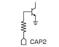 |
| VGG2 | AC Ground | This pad should be attached to an off-chip bypass capacitors. The recommended bypassing for this pad is a 0.1uF+100pF. Do not ground this pad. | - |
AMM-9024CH
DC- 70GHz, Broadband Distributed Amplifier
The Absolute Maximum Ratings indicate limits beyond which damage may occur to the device. If these limits are exceeded, the device may become inoperable or have a reduced lifetime. Reliability limits are individual, instantaneous catastrophic limits only. Functional operation limits are indicated below. Operation of the device at multiple absolute maximum limits or for extended periods at a single limit can cause degradation and damage to the device.
| Parameter | Maximum Rating | Unit |
|---|---|---|
| Drain Supply Voltage (Vd) | 7 | V |
| Gate Supply Voltage (Vg) | -1.5 | V |
| Maximum Operating Temperature for MTTF > 1E6 hours | 85 | °C |
| Maximum Storage Temperature | 125 | °C |
| Minimum Operating Temperature for MTTF > 1E6 hours | -40 | °C |
| Minimum Storage Temperature | -65 | °C |
| Positive Drain Supply Current (Id) (with RF Input) | 70 | mA |
| RF Input Power | 20 | dBm |
| Parameter | Details | Rating |
|---|---|---|
| Dimensions | - | 1.35 x 1.2 mm |
The Recommended Operating Conditions indicate the limits, inside which the device should be operated, to guarantee the performance given in Electrical Specifications. Operating outside these limits may not necessarily cause damage to the device, but the performance may degrade outside the limits of the Electrical Specifications. For limits, above which damage may occur, see Absolute Maximum Ratings.
| Parameter | Min | Nominal | Max | Unit |
|---|---|---|---|---|
| Gate Bias DC Voltage (Vg) | - | -0.25 | - | V |
| Positive DC Current (Id) (No RF Input) 1 | - | 45 | - | mA |
| Positive DC Voltage (Vd) | - | 5 | - | V |
| Input Power for Saturation | - | 5 | - | - |
[1] Recommended operating current condition without RF input applied.
AMM-9024CH
DC- 70GHz, Broadband Distributed Amplifier
Unless otherwise specified, electrical specifications apply at TA=+25°C, Vd = 5V and Vg set such that Id = 45mA.
| Parameter | Test Conditions | Minimum Frequency (GHz) | Maximum Frequency (GHz) | Min | Typ | Max | Unit |
|---|---|---|---|---|---|---|---|
| Input Power for Saturation | Vd=5V, Id=45mA | 0 | 60 | - | 5 | - | dBm |
| Input Return Loss | Vd=5V, Id=45mA, Pin=-20dBm | 0 | 60 | - | 20 | - | dB |
| Noise Figure | Vd=5V, Id=45mA, Pin=-20dBm | 1 | 10 | - | 4 | - | dB |
| Noise Figure | Vd=5V, Id=45mA, Pin=-20dBm | 10 | 30 | - | 2.5 | - | dB |
| Noise Figure | Vd=5V, Id=45mA, Pin=-20dBm | 30 | 50 | - | 3 | - | dB |
| Output P1dB | Vd=5V, Id=45mA | 0 | 30 | - | 11 | - | dBm |
| Output P1dB | Vd=5V, Id=45mA | 30 | 60 | - | 8 | - | dBm |
| Output Return Loss | Vd=5V, Id=45mA, Pin=-20dBm | 0 | 60 | - | 20 | - | dB |
| Reverse Isolation | Vd=5V, Id=45mA, Pin=-20dBm | 0 | 60 | - | 40 | - | dB |
| Saturated Output Power | Vd=5V, Id=45mA | 30 | 60 | 8 | 11 | - | dBm |
| Saturated Output Power | Vd=5V, Id=45mA | 0 | 30 | 12 | 14 | - | dBm |
| Small Signal Gain | Vd=5V, Id=45mA, Pin=-20dBm | 0 | 60 | 10 | 11.5 | - | dB |
| Parameter | Test Conditions | Minimum Frequency (GHz) | Maximum Frequency (GHz) | Min | Typ | Max | Unit |
|---|---|---|---|---|---|---|---|
| Input Power for Saturation | Vd=5V, Id=45mA | 0 | 60 | - | 5 | - | dBm |
| Input Return Loss | Vd=5V, Id=45mA, Pin=-20dBm | 0 | 60 | - | 20 | - | dB |
| Noise Figure | Vd=5V, Id=45mA, Pin=-20dBm | 1 | 10 | - | 4 | - | dB |
| Noise Figure | Vd=5V, Id=45mA, Pin=-20dBm | 10 | 30 | - | 2.5 | - | dB |
| Noise Figure | Vd=5V, Id=45mA, Pin=-20dBm | 30 | 50 | - | 3 | - | dB |
| Output P1dB | Vd=5V, Id=45mA | 0 | 30 | - | 11 | - | dBm |
| Output P1dB | Vd=5V, Id=45mA | 30 | 60 | - | 8 | - | dBm |
| Output Return Loss | Vd=5V, Id=45mA, Pin=-20dBm | 0 | 60 | - | 20 | - | dB |
| Reverse Isolation | Vd=5V, Id=45mA, Pin=-20dBm | 0 | 60 | - | 40 | - | dB |
| Saturated Output Power | Vd=5V, Id=45mA | 30 | 60 | 8 | 11 | - | dBm |
| Saturated Output Power | Vd=5V, Id=45mA | 0 | 30 | 12 | 14 | - | dBm |
| Small Signal Gain | Vd=5V, Id=45mA, Pin=-20dBm | 0 | 60 | 10 | 11.5 | - | dB |
AMM-9024CH
DC- 70GHz, Broadband Distributed Amplifier
Performance plots measured using the recommended application circuit shown below.


AMM-9024CH
DC- 70GHz, Broadband Distributed Amplifier

AMM-9024CH
DC- 70GHz, Broadband Distributed Amplifier