Port Diagram

Sales: 408-778-9952 | General: 408-778-4200 | Fax: 408-778-4300
Sales & Customer Support: sales@markimicrowave.com
Tech Support: support@markimicrowave.com
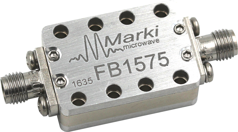
The FB series bandpass filters are CAD-optimized microstrip filter designs built on a low-loss substrate. These filters feature low insertion loss, excellent return loss and are suitable for high rejection filtering.

| Part Number | Description | Connectors | Green Status | Product Lifecycle | Export Classification |
|---|---|---|---|---|---|
| FB-1575 | 15.75 GHz Bandpass Filter | Standard | Non-RoHS |
Released | EAR99 |
| Part Number | Description | Connectors | Green Status | Product Lifecycle | Export Classification |
|---|---|---|---|---|---|
| FB-1575 | 15.75 GHz Bandpass Filter | Standard | Non-RoHS |
Released | EAR99 |
FB-1575
15.75 GHz Bandpass Filter
FB-1575
15.75 GHz Bandpass Filter
| Port | Function | Connector Type | Description | Equivalent Circuit for Package |
|---|---|---|---|---|
| Port 1 | Input/Output | SMAF | Port 1 is DC open to Port 2 and GND. GND is provided through the case and RF connectors. | 
|
| Port 2 | Input/Output | SMAF | Port 2 is DC open to Port 1 and GND. GND is provided through the case and RF connectors. |
|
FB-1575
15.75 GHz Bandpass Filter
| Parameter | Maximum Rating | Unit |
|---|---|---|
| Power Handling | 1 | W |
| Parameter | Details | Rating |
|---|---|---|
| Weight | - | 22g |
| Dimensions | - | 27.94 X 18.80 mm |
FB-1575
15.75 GHz Bandpass Filter
Specifications guaranteed from -55 to +100°C, measured in a 50Ω system.
| Parameter | Test Conditions | Minimum Frequency (GHz) |
Maximum Frequency (GHz) |
Min | Typ | Max | Unit |
|---|---|---|---|---|---|---|---|
| 1 dBc Passband | Configuration A, 25°C |
14.46 | 17.06 | - | - | - | GHz |
| 30 dBc Rejection Point | Configuration A, 25°C |
11.36 | 19.31 | - | - | - | GHz |
| 3 dBc Passband | Configuration A, 25°C |
14.06 | 17.36 | - | - | - | GHz |
| Center Freq | Configuration A, 25°C |
- | - | - | 15.75 | - | GHz |
| Group Delay | Configuration A, 25°C |
- | - | - | 390.93 | - | ps |
| Insertion Loss @ F𝒸 | Configuration A, 25°C |
- | - | - | 2 | 3 | dB |
| Passband | Configuration A, 25°C |
- | - | 14.5 | - | 17 | GHz |
| Passband Return Loss | Configuration A, 25°C |
14.5 | 17 | 10 | 15 | - | dB |
| Stopband Suppression | Configuration A, 25°C |
9.5 | 21.2 | 40 | 50 | - | dB |
| Stopband Suppression | Configuration A, 25°C |
11.4 | 19.3 | 25 | 30 | - | dB |
FB-1575
15.75 GHz Bandpass Filter

FB-1575
15.75 GHz Bandpass Filter
